Receiving apparatus, receiving system using this receiving apparatus, and receiving method thereof
A receiving device and a technology for receiving signals, which are applied in transmission systems, two-way working systems, and TV system scanning details, etc., can solve problems such as high cost and increased circuit scale, and achieve low power consumption, reduced circuit scale, and ease of timing. The effect of restriction
- Summary
- Abstract
- Description
- Claims
- Application Information
AI Technical Summary
Problems solved by technology
Method used
Image

Examples
Embodiment 1
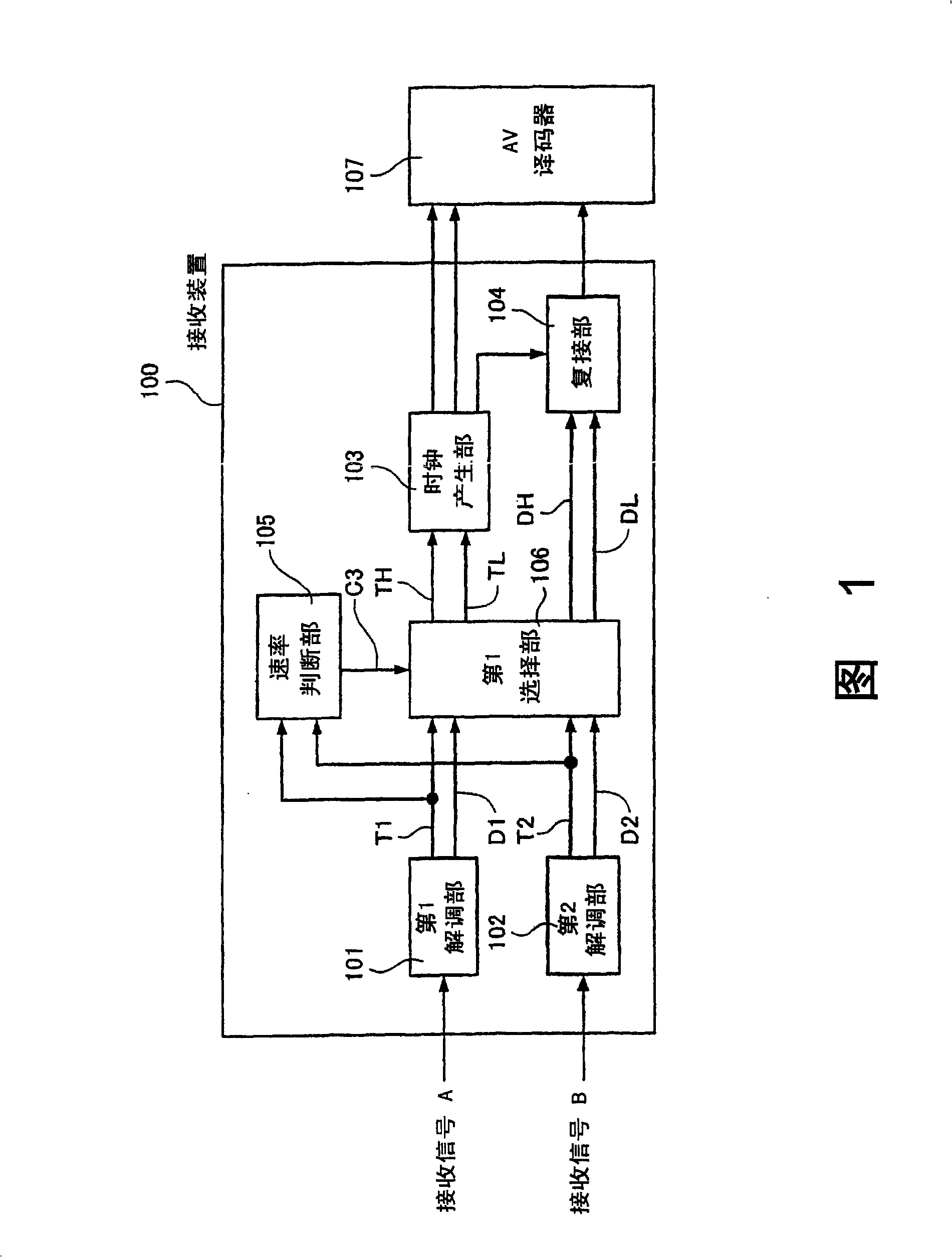
[0031] FIG. 1 is a block diagram of a receiving apparatus according to Embodiment 1 of the present invention.
[0032] In FIG. 1 , 100 is a receiving device. The receiving device 100 receives two reception signals A and B of digital broadcasting in different broadcasting systems or in the same broadcasting system, and outputs multiplexed data obtained by multiplexing the respective demodulated data outputs, and the multiplexed data. High-speed timing clock and low-speed timing clock connected to data synchronization. 107 is an AV decoder (an example of a video signal processing device). This AV decoder 107 takes the multiplexed data output from the receiving device 100, the high-speed timing clock, and the low-speed timing clock as inputs, and separates the multiplexed data into After the two demodulated data are decoded, one or both of the two demodulated data is used as received data to process the video and audio signals for each broadcast.
[0033] The receiving device 10...
Embodiment 2
[0069] Next, a receiving apparatus and a receiving method according to Embodiment 2 of the present invention will be described with reference to FIG. 5 to FIG. 8 and FIG. 3 . Components that are the same as those of Example 1 in FIGS. 1 and 3 are denoted by the same reference numerals, and explanations thereof are omitted.
[0070] In the second embodiment, a clock generation unit 501 is provided instead of the clock generation unit 103 of the first embodiment, and a multiplexing unit 503 is provided instead of the multiplexing unit 104 .
[0071]The clock generation part 501 of the second embodiment takes the count values N1 and N2 from the rate judging part 105, the control signals (initialization signals) C1 and C2, and the control signal (identification signal) C3 as inputs, and the first selection part 106 After the high-speed timing clock TH is input, the high-speed timing clock TH is output as a high-speed timing clock, and a clock whose average frequency is equal to ...
Embodiment 3
[0093] Next, a receiving apparatus according to Embodiment 3 of the present invention will be described with reference to the drawings. Components that are the same as those in Embodiment 1 in FIG. 1 are designated with systematic symbols, and explanations thereof are omitted.
[0094] Fig. 9 is a composition diagram of a receiving device according to Embodiment 3 of the present invention.
[0095] Receiving device 100 includes demodulation units 101 and 102 , first and second data expansion units 901 and 902 , control signal generation unit 903 , multiplexing unit 904 , clock generation unit 905 , and clock generation unit 906 .
[0096] The first and second data expansion parts 901 and 902 respectively input demodulation data D1 and D2 and timing clocks T1 and T2 synchronized with them from the demodulation parts 101 and 102, and output them alternately in units of one cycle, thereby timing Clocks T1, T2 are divided into timing clocks T1a, T1b, T2a, T2b and output. Moreove...
PUM
 Abstract
Description
Claims
Application Information
 - R&D
- Intellectual Property
- Life Sciences
- Materials
- Tech Scout
- Unparalleled Data Quality
- Higher Quality Content
- 60% Fewer Hallucinations
Browse by: Latest US Patents, China's latest patents, Technical Efficacy Thesaurus, Application Domain, Technology Topic, Popular Technical Reports.
© 2025 PatSnap. All rights reserved.Legal|Privacy policy|Modern Slavery Act Transparency Statement|Sitemap|About US| Contact US: help@patsnap.com