
Liquid sprayer

A technology of liquid spraying and liquid, which is applied in the direction of liquid spraying device, spraying device, spraying device with movable outlet, etc., and can solve problems such as leakage

Inactive Publication Date: 2009-01-14
AU OPTRONICS CORP
View PDF10 Cites 0 Cited by
  • Summary
  • Abstract
  • Description
  • Claims
  • Application Information

AI Technical Summary

Problems solved by technology

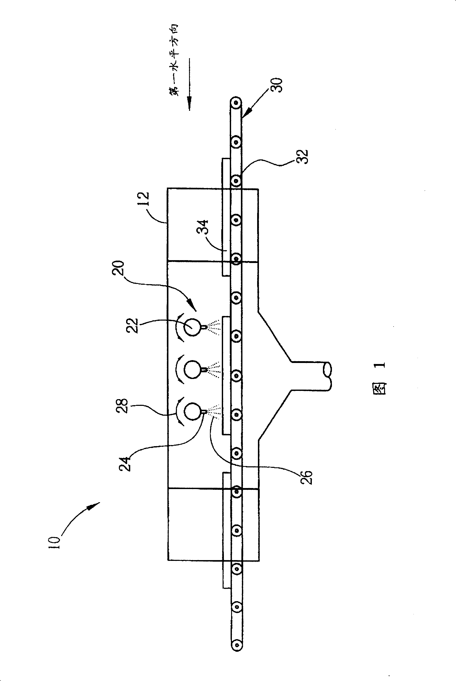
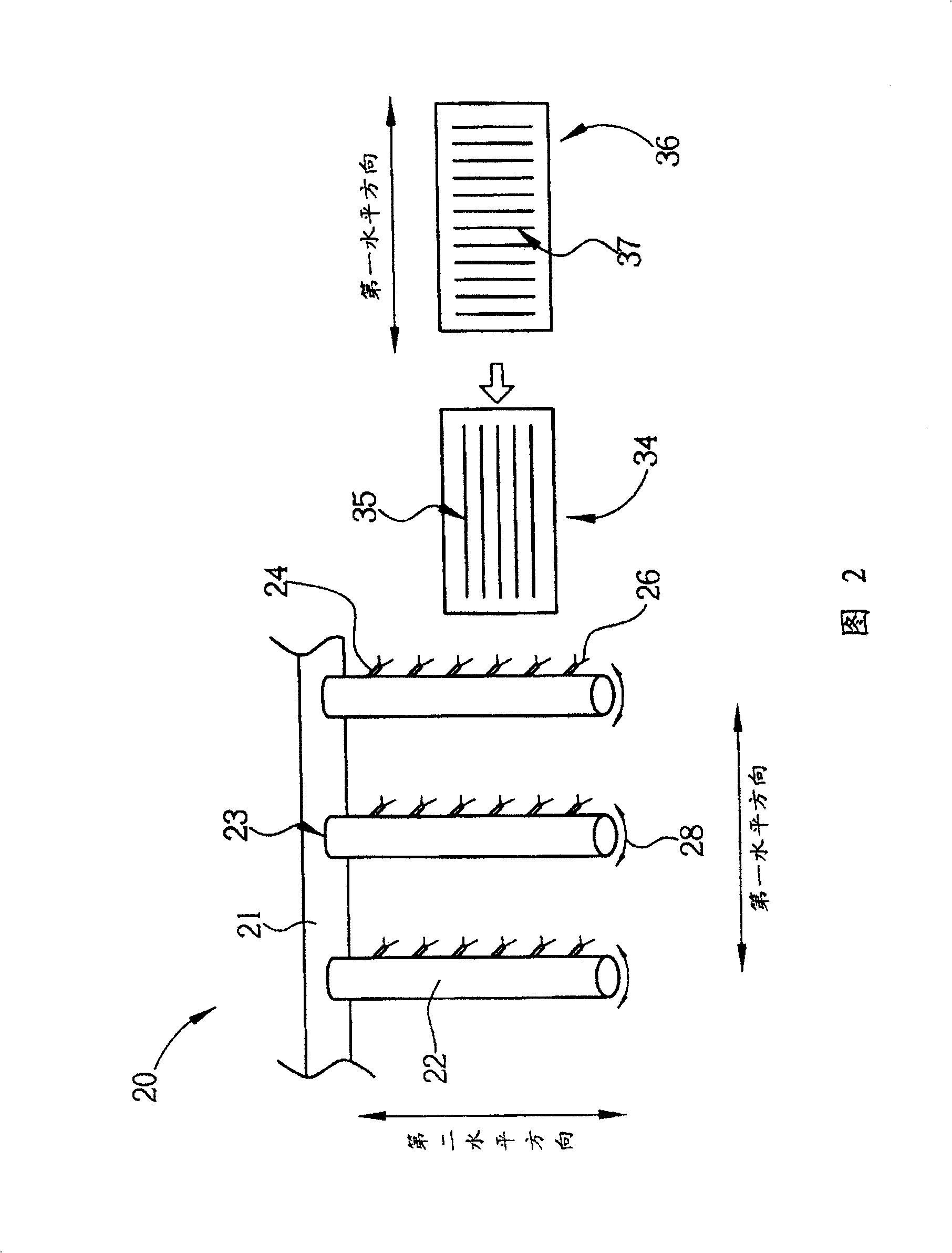
Since each water supply pipe 22 rotates alternately clockwise and counterclockwise with its rotating shaft as the center and in the direction of the arrow 28, there will often be leakage at the joint 23 between the water supply pipe 22 and the main pipe 21. This is the existing liquid Another disadvantage of sprinkler 10

Method used


Image

  • Liquid sprayer
  • Liquid sprayer
  • Liquid sprayer

Examples


Embodiment Construction

[0031] Please refer to Figure 3 to Figure 4. 3 is a schematic side view of the liquid spraying device 40 of the present invention spraying liquid on the substrate 47 , and FIG. 4 is a block diagram of the driving device 60 of the liquid spraying device 40 in the wet manufacturing process of the present invention.

[0032] As shown in FIG. 3 , the liquid spraying device 40 of the present invention includes a casing 41 including a hollow inner chamber 42 . A bottom side of the inner compartment 42 is provided with a base 44 for horizontally placing a base plate 47 . The liquid spraying device 40 also includes several round pipes 50 installed horizontally on the upper side of the inner cabin 42 for transmitting a specific liquid 51. A plurality of delivery pipes 55 are vertically arranged on the upper side of the inner cabin 42 and fixed on multiple Below the root tube 50, a nozzle 54 is provided at the lower end of each delivery pipe 55 for spraying liquid 51 downwards, a conne...


PUM


Abstract

The liquid sprayer for cleaning, development, etching and other wet process includes a casing with hollow compartment, several conveying pipes set to the compartment vertically, several nozzles below the pipes a connector to drive the conveying pipes for spraying liquid toward the same direction, a driver to drive the connector to move in different direction, a horizontal pedestal inside the compartment for setting substrate.

Description

technical field [0001] The present invention relates to a liquid spraying device, in particular to a multi-directional liquid spraying device used in wet manufacturing processes such as cleaning, developing or etching. Background technique [0002] Liquid spraying devices are widely used in various industrial wet fabrication processes, such as cleaning, developing, or etching processes. The existing liquid spraying device in the wet production process includes a housing containing liquid spraying equipment, a liquid supply system containing a plurality of water supply pipes and a plurality of nozzles arranged on the lower side thereof, and a conveying line for transporting the substrate sprayed by the liquid, A driving device is used to drive the spraying movement. With the complexity and diversification of the substrate design, the single-direction spraying liquid spraying device may not be able to efficiently complete the wet fabrication process of the substrate. How to ...

Claims


Application Information

Patent Timeline
Patent Type & Authority Patents(China)
IPC IPC(8): G03F7/30G03D5/04B05B9/03B05B3/18
Inventor 林育民
Owner AU OPTRONICS CORP
Learn More