
Flexible soft tube

A flexible, flexible hose technology, applied in the direction of hose, pipe, pipe/pipe joint/pipe fitting, etc., can solve the problems of reducing air barrier and difficult to ensure flexibility.

Inactive Publication Date: 2009-01-07
TOTAKU IND INC
View PDF4 Cites 2 Cited by
  • Summary
  • Abstract
  • Description
  • Claims
  • Application Information

AI Technical Summary

Problems solved by technology

[0009] However, since the resin with gas barrier properties is generally a hard resin, it is difficult to ensure sufficient flexibility when the gas barrier layer is formed into a tubular shape with substantially smooth inner and outer sides by extrusion molding.
In addition, if the gas-barrier layer is made into an extremely thin film to improve flexibility, the gas-barrier property will be lowered conversely.

Method used


Image

  • Flexible soft tube
  • Flexible soft tube
  • Flexible soft tube

Examples


Embodiment Construction

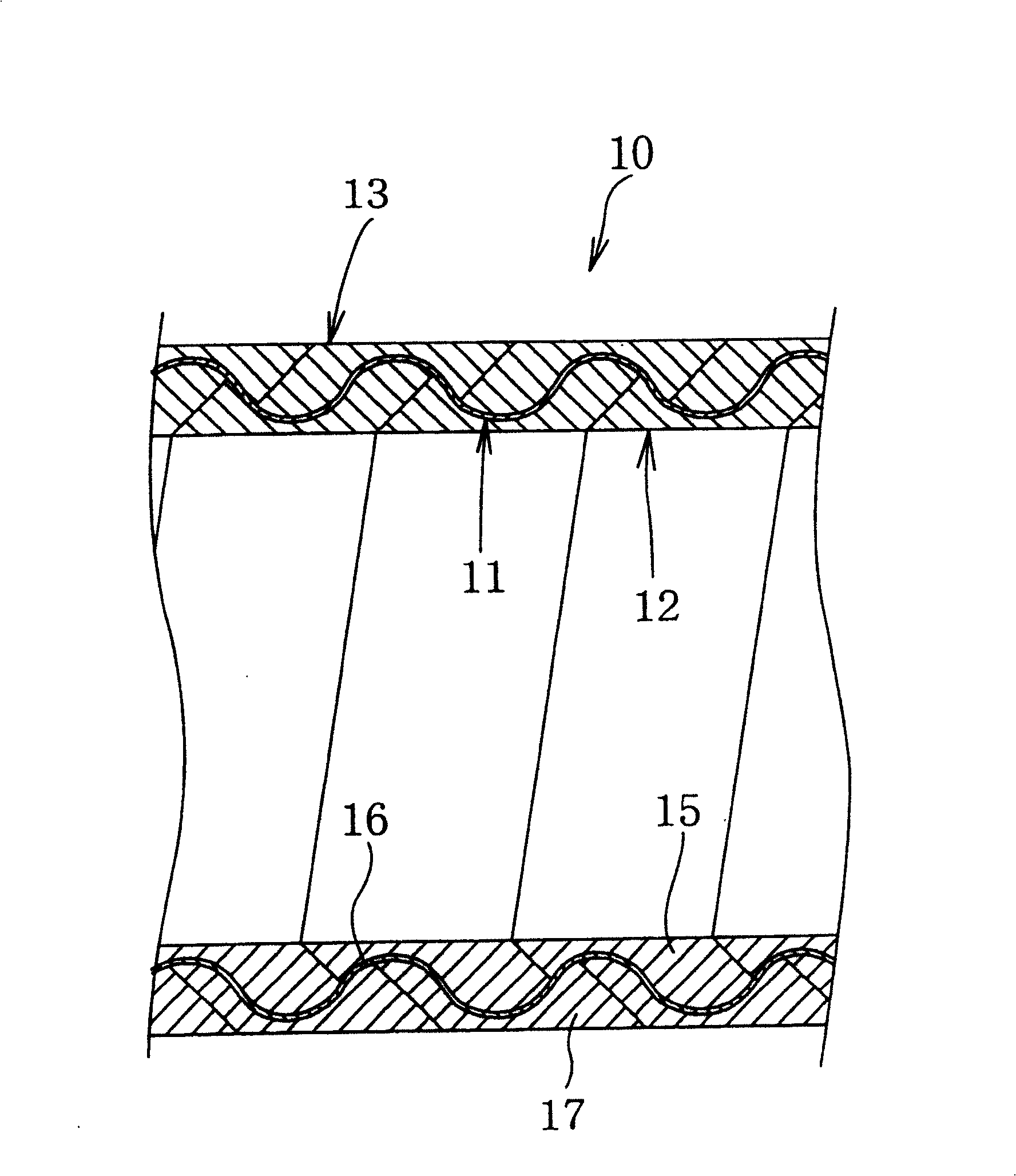
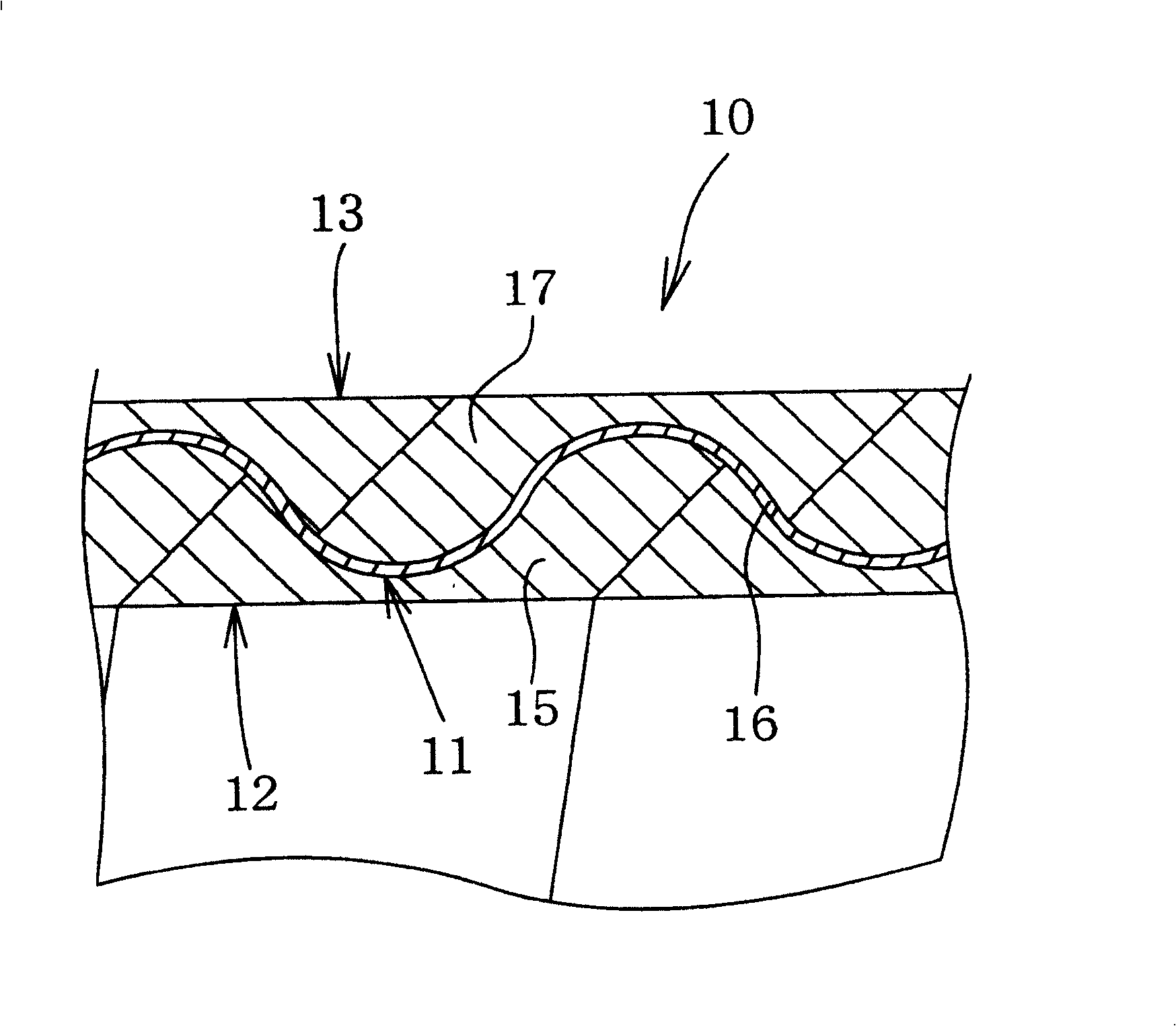
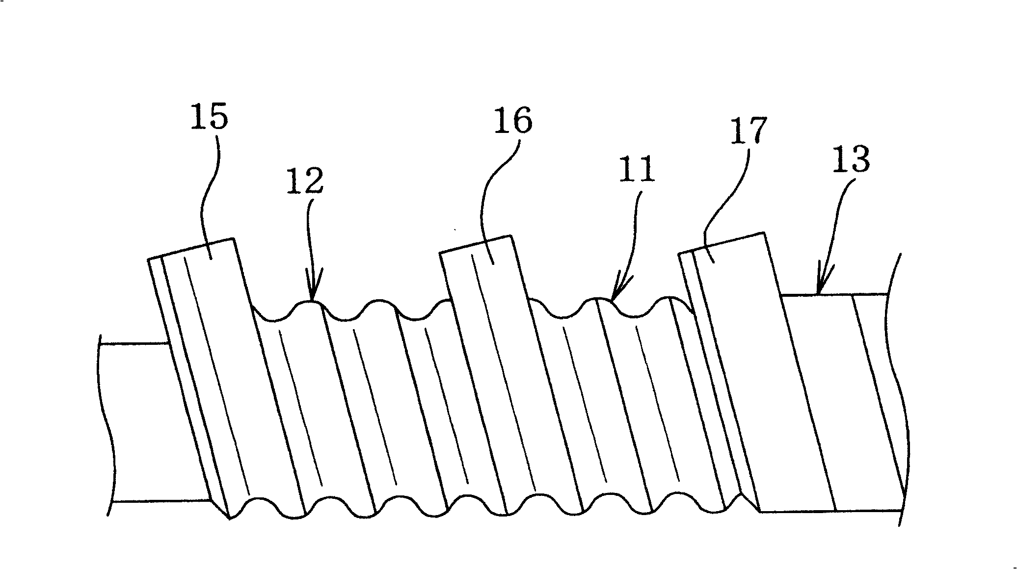
[0022] Embodiments of the present invention will be described in detail below based on the drawings. Such as figure 1 as well as figure 2 As shown, in the flexible hose in one embodiment of the present invention, the middle resin layer 11 is pinched in the inner and outer resin layers 12, 13 and these resin layers 11, 12, 13 are laminated in the radial direction. into the hose wall 10.

[0023] The intermediate resin layer 11 is a hard gas-barrier layer formed of a resin with gas-barrier properties, such as nylon 6, to ensure the rigidity and shape retention of the hose. The intermediate resin layer 11 has a certain thickness, and forms a concavo-convex continuous wave along the axial direction. Therefore, good flexibility is maintained without impairing the gas barrier properties. In addition, although the intermediate resin layer 11 is formed with concavities and convexities on both its inner and outer peripheral surfaces, it is also possible to form continuous concavo...


PUM


Abstract

A flexible hose of the invention has a hose wall which is formed by laminating resin layers. The resin layer acting as a gas barrier is formed by spirally winding a gas barrier resin strip and thermally fusing or bonding axially adjoining edges of the strip to each other. The resin layers are thermally fused or bonded to one another to become one piece.

Description

technical field [0001] The present invention relates to a flexible hose with excellent gas barrier properties that is most suitable for various hoses that require blocking of gas, such as food transport hoses, liquid fuel transport hoses, and refrigerant transport hoses. Background technique [0002] As a flexible hose with gas barrier properties, such as Figure 4 Shown is a structure in which steel wires 2 and 2 are wound around the inner and outer peripheral surfaces of a laminated body 1 having gas barrier properties. The laminated body 1 is constituted by laminating a resin film having gas-barrier properties into a tape having a predetermined width, and winding it in multiple layers in a cylindrical shape. The steel wires 2, 2 clamp the stacked body 1 to prevent the stacked body 1 from being uneven. Such a flexible hose is disclosed in Patent Document 1, for example. [0003] In addition, as other flexible hoses with gas barrier properties, such as Figure 5 As shown...

Claims


Application Information

Patent Timeline
Patent Type & Authority Patents(China)
IPC IPC(8): F16L11/06F16L11/12B32B1/08B32B27/00F16L11/24
CPCF16L11/24B32B3/28B32B27/08B32B27/36B32B27/40B32B2307/7242F16L11/088F16L11/115
Inventor 福井弘毅进藤信夫池上宽橘茂人
Owner TOTAKU IND INC
Learn More