


Quick Research
Generate reliable direction feasibility study reports for your R&D in just a few steps.

Technical Q&A
Discover and master advanced knowledge NOW. Basics, ideas, possibilities, all at once.

Find Solutions
As an expert in R&D theories, this can generate solutions to your technical problems instantly.

Evaluate Feasibility
Analyze your overall solution with one click, know your potential R&D risks in advance.

Monitor Landscape
Get weekly tech updates, stay abreast of the latest tech innovations and key insights.
Curvilinear optical modulation component and backlight module with same
A technology of optical modulation and backlight module, applied in nonlinear optics, optics, instruments, etc., can solve problems such as high difficulty in array structure processing, unsuitable for mass production, moiré, etc.
- Summary
- Abstract
- Description
- Claims
- Application Information
AI Technical Summary
Problems solved by technology
Method used
Image

Examples
Embodiment 1
[0034] Figure 3A to Figure 5 It is a drawing drawn according to Embodiment 1 of the curved optical modulation element and the backlight module having the modulation element of the present invention.
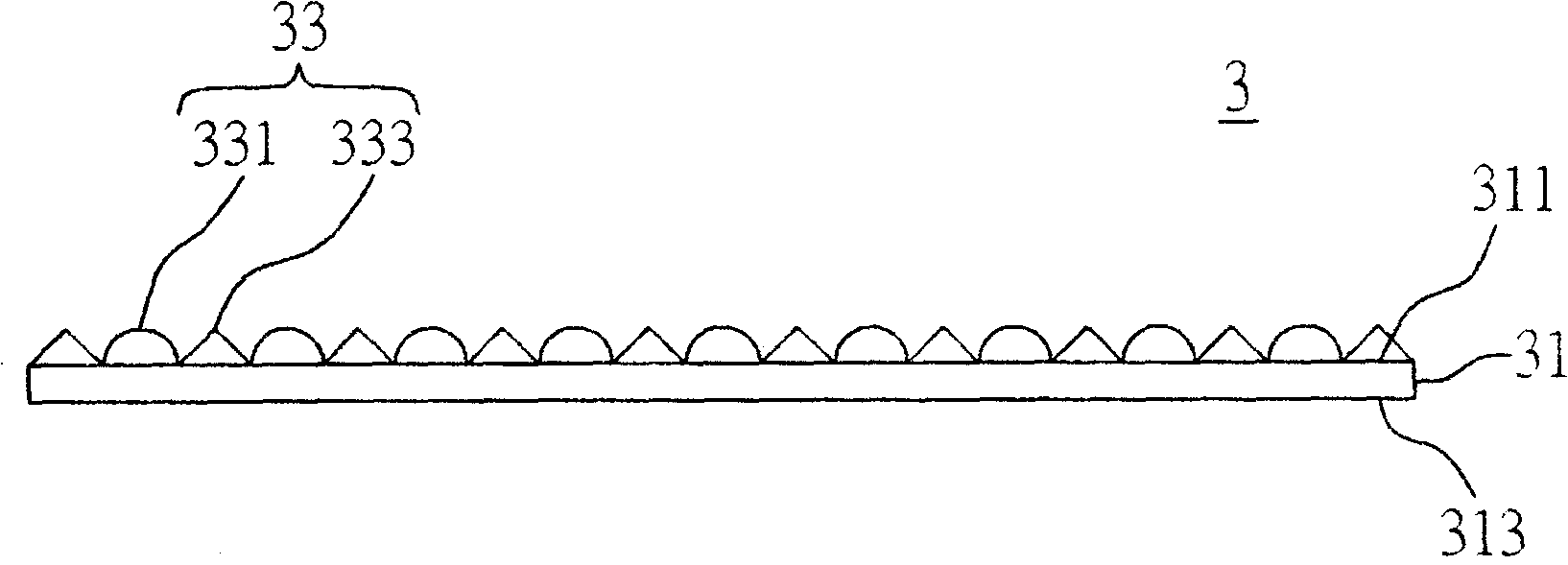
[0035] see Figure 3A , which is a cross-sectional view of the structure of the curved optical modulation element of the first embodiment. The curved optical modulation element 3 shown in the figure includes a light-transmitting substrate 31 and a curved microstructure 33 . Wherein the curve may be a curve function such as a trigonometric function sin(x), cos(x) and the like.
[0036] The transparent substrate 31 has a first optical surface 311 and a second optical surface 313 opposite to each other. In the first embodiment, the light-transmitting substrate 31 may be a transparent substrate, a transparent film or other equivalent transparent elements. The second optical surface 313 can be selected as a smooth optical surface or an optical surface with a rough undulating stru...
Embodiment 2
[0047] Figure 6A to Figure 7 It is a drawing according to Embodiment 2 of the curved optical modulation element and the backlight module with the modulation element of the present invention. Wherein, the same or similar components as in Embodiment 1 are represented by the same or similar component symbols, and detailed descriptions are omitted to make the description of this case clearer and easier to understand.
[0048] The biggest difference between embodiment 2 and embodiment 1 is that, in the curved optical modulation element of embodiment 2, the extension direction of the curve of the diffusion part and the light collection part is perpendicular to the first optical surface, and the backlight module also includes A reflection sheet located under the light guide plate.
[0049] see Figure 6A Fig. 1 is a cross-sectional view of the structure of the curved optical modulation element of the second embodiment. In the curved optical modulation element 3 of Embodiment 2, t...
Embodiment 3
[0052] Figure 8 to Figure 9 It is a drawing according to Embodiment 3 of the curved optical modulation element and the backlight module with the modulation element of the present invention. Wherein, the same or similar components as those in the above-mentioned embodiments are denoted by the same or similar component symbols, and detailed descriptions are omitted.
[0053] The biggest difference between Embodiment 3 and the above embodiments is that the diffusion part and the light collecting part are arranged in equal proportions and spaced side by side, and the difference from Embodiment 2 is that the backlight module also includes a curved optical modulation element. protective film.
[0054] see Figure 8 , in the curved optical modulation element 3 of the third embodiment, the diffusing portion 331 and the light collecting portion 333 are arranged side by side at equal intervals, for example, two light collecting portions 333 are matched with two diffusing portions 331...
PUM
 Abstract
Description
Claims
Application Information
 - R&D Engineer
- R&D Manager
- IP Professional
- Industry Leading Data Capabilities
- Powerful AI technology
- Patent DNA Extraction
Browse by: Latest US Patents, China's latest patents, Technical Efficacy Thesaurus, Application Domain, Technology Topic, Popular Technical Reports.
© 2024 PatSnap. All rights reserved.Legal|Privacy policy|Modern Slavery Act Transparency Statement|Sitemap|About US| Contact US: help@patsnap.com