Digital control tooth crest chamfering machine for curved tooth and angle gear

A technology of spiral bevel gear and chamfering machine, which is applied in gear tooth manufacturing device, gear tooth, gear cutting machine, etc., can solve the problem of difficult grinding, low production efficiency of manual grinding, difficult to ensure grinding consistency and other problems. Uniformity and other issues, to achieve the effect of good effect, reasonable design structure and reliable operation

Inactive Publication Date: 2008-12-17
TIANJIN NO 1 MACHINE TOOL WORKS
View PDF6 Cites 0 Cited by
  • Summary
  • Abstract
  • Description
  • Claims
  • Application Information

AI Technical Summary

Problems solved by technology

However, even if it is manual grinding, it is difficult to ensure the consistency and uniformity of grinding. When using manual chamfering, it is easy to have less grinding in the middle and more grinding at both ends for the concave surface 47, and more grinding for the convex surface. 48 is the situation where there is more grinding in the middle and less grinding at both ends
It is difficult to achieve grinding by machining, and the production efficiency of manual grinding is also low

Method used


Image

  • Digital control tooth crest chamfering machine for curved tooth and angle gear
  • Digital control tooth crest chamfering machine for curved tooth and angle gear
  • Digital control tooth crest chamfering machine for curved tooth and angle gear

Examples


Embodiment Construction

[0047] Next, the CNC spiral bevel gear addendum chamfering machine of the present invention will be described in detail in conjunction with the accompanying drawings and specific embodiments.

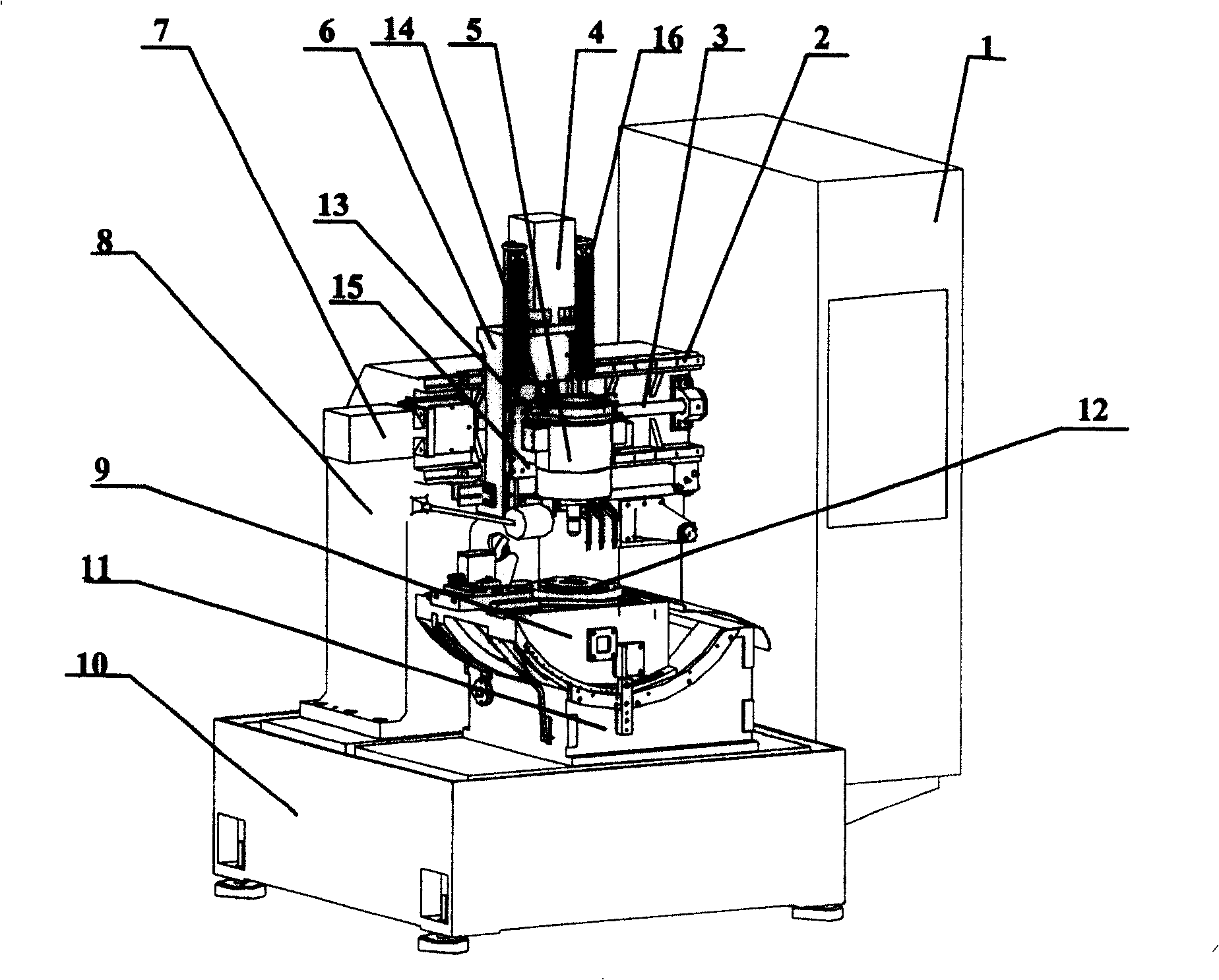
[0048] Such as figure 2 As shown, the CNC spiral bevel gear addendum chamfering machine of the present invention includes: a fuselage 10 and an electric control cabinet 1, a column 8 arranged on the fuselage 10, and a column 8 arranged on the fuselage 10 and located at the column 8 The turning table base 11 on the front side and the turning table 9 installed on the turning table base 11 are provided with a horizontal movement mechanism and a vertical movement mechanism on the column 8, and the vertical movement mechanism is arranged on the column 8 through the horizontal movement mechanism. Above, the vertical movement mechanism is provided with a grinding head mechanism 5 for chamfering the spiral bevel gear, and a spindle for installing the gear to be processed is installed at the po...


PUM


Abstract

A CNC spiral bevel gear tooth top chamfering machine includes: a fuselage and an electric control cabinet, a column set on the fuselage, a turning table base set on the machine body, and a turning working table installed on the turning workbench base. There are horizontal movement mechanism and vertical movement mechanism on the column. The vertical movement mechanism is set on the column through the horizontal movement mechanism. The vertical movement mechanism is equipped with a grinding head mechanism for chamfering the spiral bevel gear. A main shaft for installing the gear to be processed is installed on the turning table at a position corresponding to the grinding head mechanism; the grinding head mechanism support has a plane support for connecting to the vertical slide plate and is located on the front side of the plane support and integrally formed with the plane support The arc-shaped bracket used to fix the grinding head mechanism, wherein the inner peripheral surface of the arc-shaped bracket has a convex structure. The invention solves the technical problem that the tooth top chamfering of the spiral bevel gear can only be applied manually. The design structure of this machine tool is reasonable, the work is reliable, the chamfering precision is high, the effect is good, and the efficiency is high.

Description

technical field [0001] The invention relates to a gear processing machine tool. In particular, it relates to a numerical control spiral bevel gear addendum chamfering machine with accurate processing, high precision and high efficiency. Background technique [0002] The spiral bevel gear is the gear used for the main transmission of the car, which drives the wheel to rotate through the planetary mechanism. To make a spiral bevel gear, the first step is to make a blank, rough machining and finishing machining, and then heat treatment. After heat treatment, the edge of the gear is deformed, such as figure 1 As shown, the corners 50, 49 of the gear are deformed. Moreover, there are also processing errors in the processing of spiral bevel gears. If they are not processed and used directly for automobile assembly, the deformation of the edges will inevitably increase the noise when the automobile is running. [0003] In order to ensure that there is no error in the edge positi...

Claims


Application Information

Patent Timeline
Patent Type & Authority Patents(China)
IPC IPC(8): B23F19/12B23F23/02B23Q1/25B24B9/00
Inventor 柴宝莲胡光曦崔援朝
Owner TIANJIN NO 1 MACHINE TOOL WORKS
Why Eureka
Try Eureka