
Programmable controller system

A programming controller and memory technology, applied in electrical program control, program control in sequence/logic controllers, etc., can solve the problem that the reliability of time difference data is not guaranteed.

Active Publication Date: 2008-12-10
ORMON CORP
View PDF7 Cites 0 Cited by
  • Summary
  • Abstract
  • Description
  • Claims
  • Application Information

AI Technical Summary

Problems solved by technology

[0011] Therefore, if there are multiple remote control input and output devices, and there are multiple deterioration diagnosis objects on each, it is necessary to set Figure 10 The program shown is described in the user program, which requires a lot of labor
In addition, by adding a program for such a login process, the amount of the overall user program also increases, and the cycle time of the PLC device side is slightly different from the cycle time of the system application. The reliability of the time difference data acquired in this state not necessarily guaranteed

Method used


Image

  • Programmable controller system
  • Programmable controller system
  • Programmable controller system

Examples


Embodiment Construction

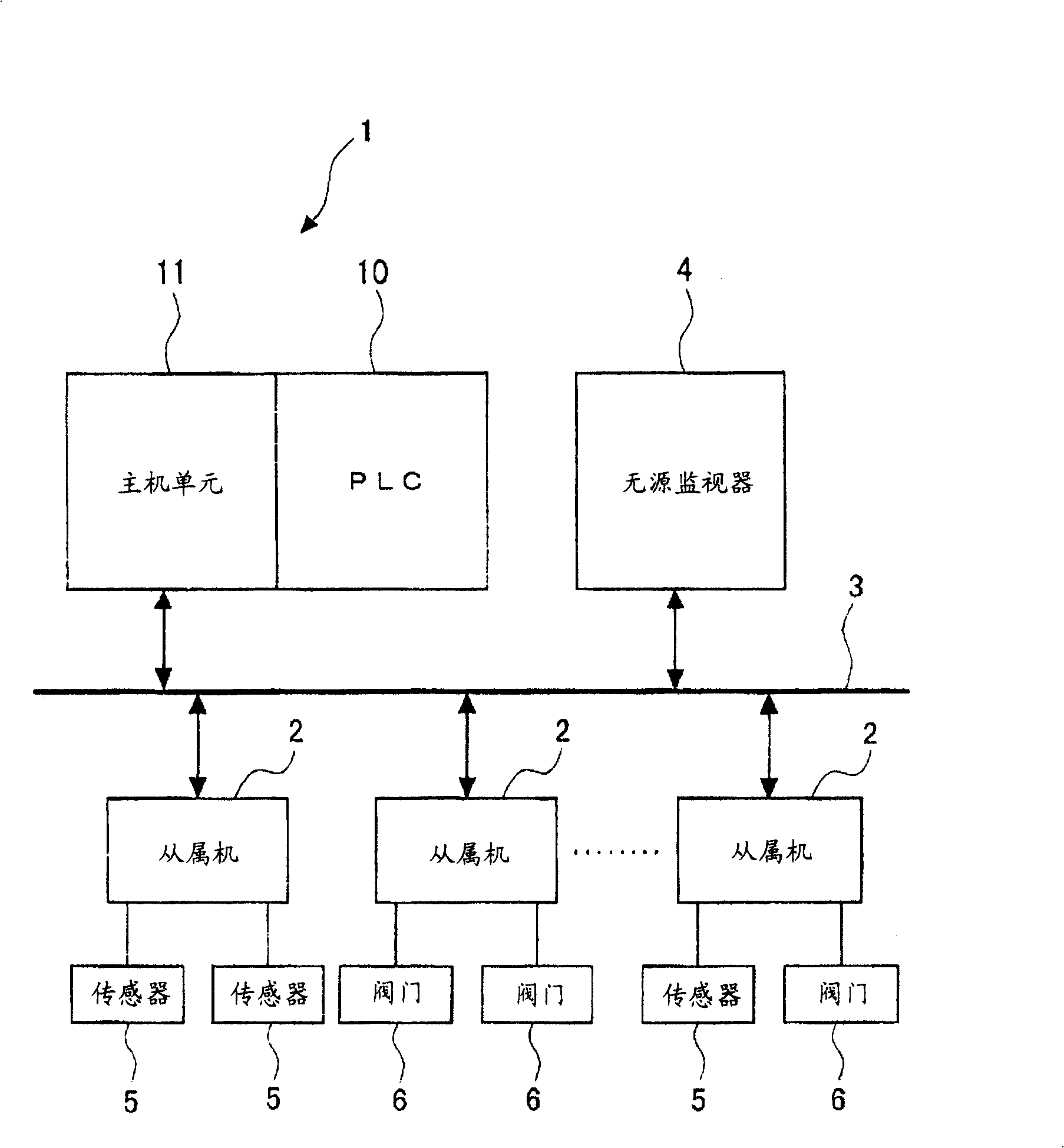
[0075] Hereinafter, preferred embodiments of the present invention will be described in detail with reference to the drawings. The structure of the PLC system of the present invention is shown in figure 1 .

[0076] As shown in the figure, the PLC system connects the PLC device 1 and a plurality of slave machines (remote control input and output devices) 2 in a communication manner through a field bus, and at the same time, on the communication path connecting the PLC device 1 and the slave machines 2, There is provided a passive monitor 4 which can passively monitor the communication data flowing between them.

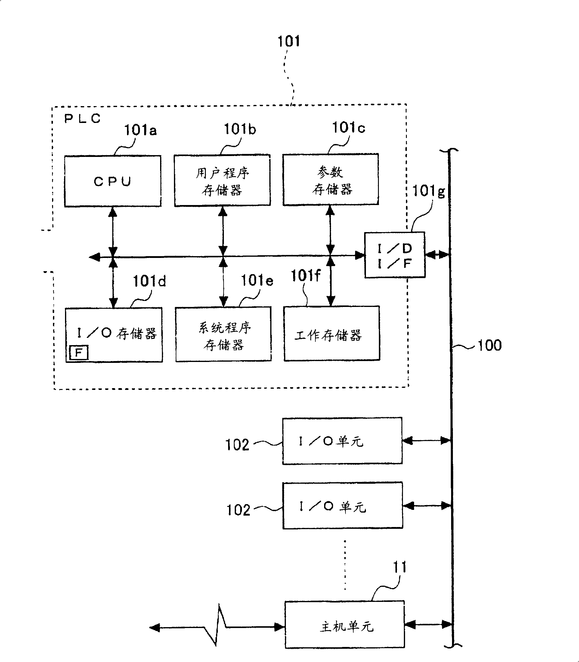
[0077] In this example, the PLC device 1 includes a PLC 10 and a host unit 11 . like figure 2 As shown, the PLC device 10 includes: a CPU unit 101 for centrally controlling the PLC as a whole; / O units 102, 102....

[0078] like figure 2 As shown, the CPU unit 101 includes: a CPU 101a, which centrally controls the overall operation of the CPU; a program memor...


PUM


Abstract

By reducing the labor involved in determining thresholds during the introduction of a PLC system with an external device degradation diagnosis function, and ensuring the same operation during system introduction and system application, highly reliable data can be collected. In a device that is located on a communication path between a programmable controller device and a remote control input / output device and can passively monitor the communication data flowing between them, an external device degradation diagnosis is associated with each degradation The diagnosis sets a rewritable flag that specifies the conditions under which the transmission request command is issued, and by referring to the flag, the command issuance unit issues the transmission request command to the remote control input and output device. Therefore, in this device, the required data registration operation is performed appropriately without interfering with the PLC.

Description

technical field [0001] The present invention relates to a programmable controller system, which can directly refer to the deterioration diagnosis result in a ladder diagram mode by notifying the deterioration diagnosis result of external equipment performed on the remote control input and output device side to the programmable controller device side through communication. Background technique [0002] The present applicant has proposed a programmable controller system (hereinafter referred to as PLC system) before this application, by notifying the programmable controller device side of the deterioration diagnosis result of the external equipment performed on the remote control input and output device side through communication, thereby It is possible to refer to the deterioration diagnosis result (for example, Patent Document 1). [0003] According to such a PLC system, as mentioned above, it is not necessary to incorporate message communication processing for taking in the...

Claims


Application Information

Patent Timeline
Patent Type & Authority Patents(China)
IPC IPC(8): G05B19/05
Inventor 上野真太郎泉谷作
Owner ORMON CORP
Learn More