Chip monitoring and breakage alarming method

A chip and overhead technology, applied in the field of optical transmission, can solve the problems of not having real-time monitoring of service flow chip damage, inability to accurately locate alarms, and loss of users.

Inactive Publication Date: 2008-12-03
ZTE CORP
View PDF3 Cites 0 Cited by
  • Summary
  • Abstract
  • Description
  • Claims
  • Application Information

AI Technical Summary

Problems solved by technology

It usually takes a long time from the occurrence of the alarm to the manual switching of the board and the disappearance of the alarm, which will cause business interruption for several minutes or even several hours, causing users to suffer losses
[0003] The root cause of this problem is that the current equipment does not have the ability to monitor whether the service flow chip is damaged in real time
The transmission protocol alarm detection provided by most service flow chips can only detect the alarm of the service flow itself, and the monitoring range of the service flow alarm is very wide, and may span multiple devices and optical fiber channels, so the alarm of the detected service flow cannot be accurately located Whether there is a chip damage in the device and the location of the chip damage, so the alarm defined in the transmission protocol provided by the current business flow chip cannot be used as a criterion for monitoring whether the chip is damaged

Method used


Image

  • Chip monitoring and breakage alarming method
  • Chip monitoring and breakage alarming method

Examples


Embodiment Construction

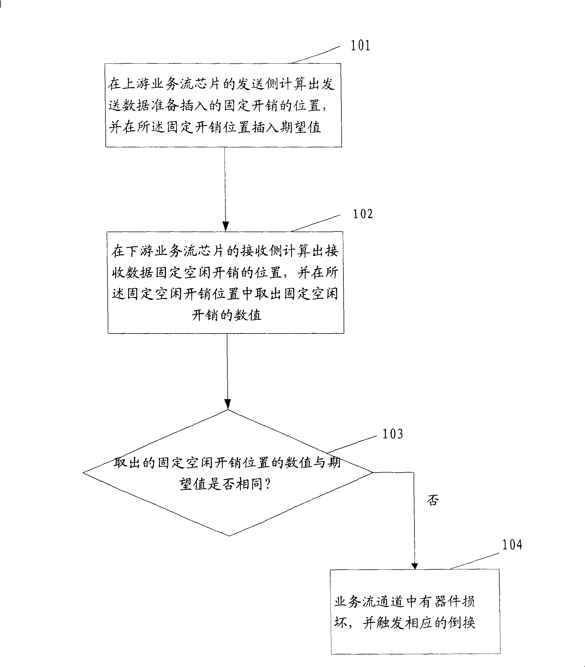
[0018] refer to figure 1 , is a flow chart of the monitoring chip damage alarm method of the present invention.

[0019] 101. On the sending side of the upstream service flow chip, calculate the position of the fixed overhead to be inserted into the sending data, and insert an expected value in the fixed idle overhead position;

[0020] Here, the fixed idle overhead position refers to an overhead byte in the transmission service stream; the insertion of an expected value at the fixed idle overhead position is to insert a fixed custom byte.

[0021] 102. Calculate the fixed idle overhead position of the received data at the receiving side of the downstream service flow chip, and take out the value of the fixed idle overhead from the fixed idle overhead position;

[0022] 103. Comparing the value of the fetched fixed idle overhead position with the expected value;

[0023] Insert the expected value at the fixed overhead position on the sending side of the upstream service flow...


PUM


Abstract

The invention discloses a monitoring chip damagie alarm method, which comprises the following steps: (101) calculating fixed overhead location where the sending data prepares to insert on the sending side of upper business flow clip; inserting desired value in fixed location; (102) calculating receiving data fixed free overhead location on the lower business flow clip; taking out fixed free overhead value in fixed free owerhead location; (103) comparing the taked-out fixed free overhead location value with desired value; (104) triggering corresponding rearrange, if taked out fixed free overhead location value is different from desired value, the business flow channel has damage device.

Description

technical field [0001] The invention relates to a method for monitoring chip damage and warning in the field of digital communication, in particular to a method for monitoring chip damage and warning in the field of optical transmission. Background technique [0002] At present, in optical transmission equipment, many equipment provide some single-board backup protection measures to make up for the incomplete service protection of the adopted transmission protection protocol. However, many board protection functions currently provided are very limited, except for a few power supply alarms or CPU-related chip alarms that can be detected, which will trigger automatic board switching within tens of milliseconds when an alarm occurs. In addition to the rapid recovery of services, if most of the service flow chips on the board are damaged, the automatic switching of the board cannot be triggered. Generally, when a possible alarm is found, the service can only be switched from th...

Claims


Application Information

Patent Timeline
Patent Type & Authority Patents(China)
IPC IPC(8): H04L12/24H04B1/74
Inventor 于莉柯楚
Owner ZTE CORP
Why Eureka
Try Eureka