Connector

A technology for connectors and connection objects, which is applied in the direction of connection, electrical components, coupling devices, etc., can solve the problems of low height, small displacement of the first contact part 301 and the second contact part 302, and no contact pressure.

Inactive Publication Date: 2008-11-26
SMK CO LTD
View PDF10 Cites 0 Cited by
  • Summary
  • Abstract
  • Description
  • Claims
  • Application Information

AI Technical Summary

Problems solved by technology

[0012] Therefore, in order to achieve low height, it is also conceivable to set the interval between the contact portions 111, 112 to be equal to or less than the thickness t of the FPC 107 without using the ZIF structure. When H11 becomes lower, the displacement of the contact parts 111, 112 of the first and second contacts 101, 102 also becomes smaller, and there is a problem that the specified contact pressure cannot be obtained.
[0013] Moreover, in Figure 11 In the known example of the second contact 102 formed by punching and bending a conductive plate material, the fixing piece 121 is extended along the insertion direction of the FPC 107 and fixed to the inner wall side of the upper plate of the housing 103 Therefore, there is a problem that the spring length B11 cannot be relatively longer than the insertion direction length L11 of the connector board.
[0014] In addition, in Figure 12 In the known example of the connector for flexible substrates shown, since the opposing surfaces of the contact parts 211 and 212 where the first contact 201 and the second contact 202 face each other are also formed in convex shapes, Therefore, when the height H12 becomes lower, the displacement of the first and second contacts 201, 202 also becomes smaller, and there is a problem that the specified contact pressure cannot be obtained.
[0015] In addition, in Figure 13 In the known example of the connector for flexible substrates shown, since the opposing surfaces of the first contact portion 301 and the second contact portion 302 of one set are also formed in a convex shape, when the direction perpendicular to the insertion direction of the connector When the length L13 in the direction becomes shorter, the amount of displacement between the first contact portion 301 and the second contact portion 302 also becomes smaller, and a predetermined contact pressure cannot be obtained, so there is a problem that it is difficult to shorten the length L13.
[0016] In some known connectors, one of the opposing surfaces of the contact portions of the first and second contacts is formed in a flat shape, and the other is formed in a bead shape. Such a connector also has the same problem as above.

Method used


Image

  • Connector
  • Connector
  • Connector

Examples


Embodiment

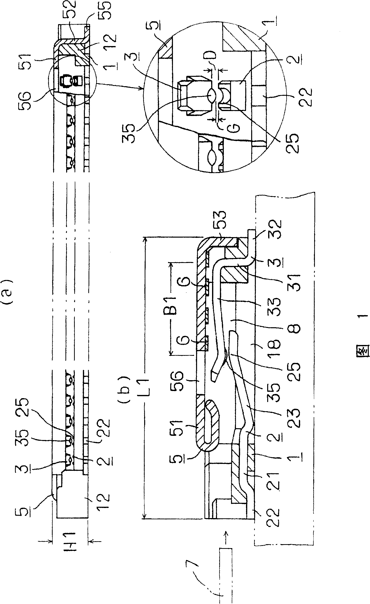
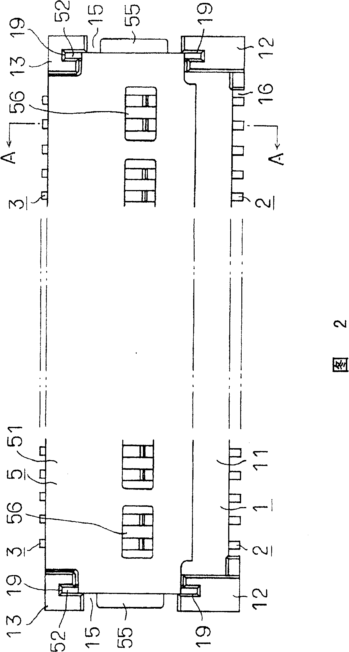
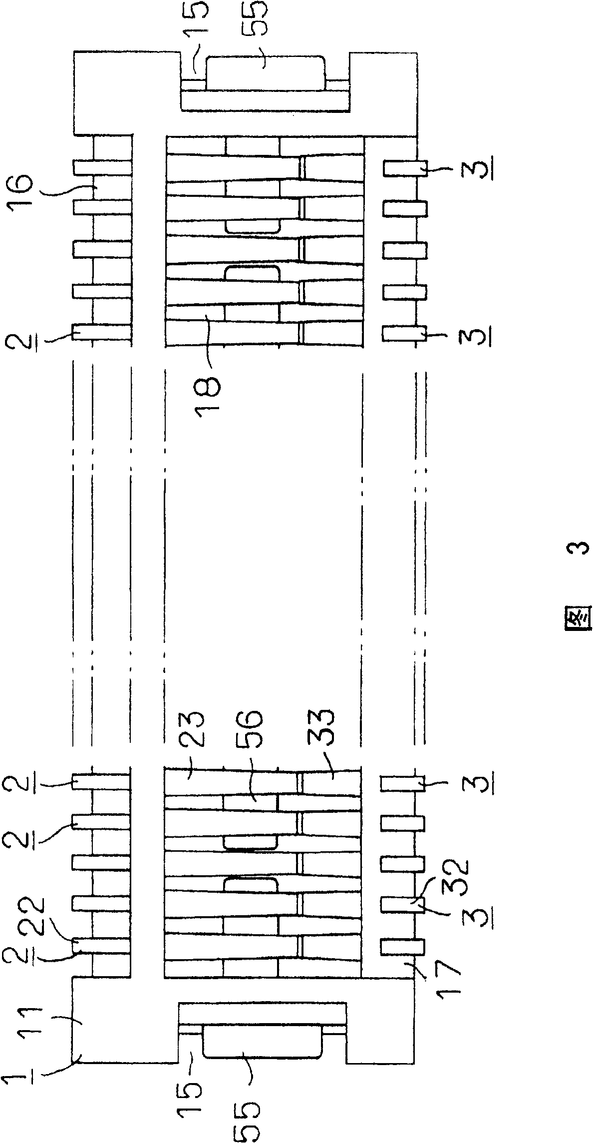
[0050] 1 to 7 show one embodiment of the connector of the present invention, that is, a connector for a flexible substrate. Contacts, 5 refer to shield fittings, 6 to 6 refer to insulating tapes, and 7 refer to FPC as an example of a flexible substrate.

[0051] The first contacts 2-2 and the second contacts 3-3 are insert-molded together with the housing 1, as shown in Figures 1 to 3, the first contacts 2 and the second contacts 3 form a group The multi-group configuration is arranged at predetermined intervals in the longitudinal direction of the housing 1 and fixed on the housing 1 .

[0052] A substrate insertion recess 8 for inserting the FPC 7 is formed between the housing 1 and the shield fitting 5 .

[0053] The casing 1 has: a base portion 11 integrally formed of an insulating synthetic resin such as LCP resin, and formed in a substantially rectangular plate shape; The two ends (the near front side of FIG. 2 ) are integrally erected, and are roughly prism-shaped; th...


PUM


Abstract

PROBLEM TO BE SOLVED: To provide a connector realized small in size and capable of making large displacement amount of contacts. ŽSOLUTION: This is the connector (for example, connector for board) in which a plurality of contacts supported at a housing 1 are constructed of a plurality of sets making a first contact 2 and a second contact 3 one set, and a first contact part 25 of the first contact 2 and a second contact part 35 of the second contact 3 are opposed to each other in non-contact state, and elastically contact the both sides of a connecting object by being displaced by the connecting object (for example, FPC 7) inserted between the opposed faces. The opposed faces of the first contact part 25 and the second contact part 35 are formed in a concavo-convex shape with the spacing in the displacement direction nearly constant. Ž

Description

technical field [0001] The present invention relates to a device for connecting a flexible substrate such as a flexible printed wiring board (hereinafter referred to as FPC) or a flexible flat cable (hereinafter referred to as FFC), a rigid printed wiring board, or a connector, to a A connector that electrically connects rigid printed wiring boards, such as the main printed wiring board, together. Background technique [0002] Among the conventional connectors for flexible substrates, known connectors have the following zero insertion force (hereinafter abbreviated as ZIF) structure: when a flexible substrate is inserted, it can be inserted from the contact with a low insertion force without being affected by contact pressure. , when the flexible substrate is inserted into contact with the contacts with a specified contact pressure, a stable electrical connection is obtained. [0003] For example Figure 11 As shown, it has: a housing 103, which supports multiple sets of co...

Claims


Application Information

Patent Timeline
Patent Type & Authority Patents(China)
IPC IPC(8): H01R12/08H01R12/28H01R12/38H01R12/79
Inventor 大泽文雄浅井清
Owner SMK CO LTD
Why Eureka
Try Eureka