
Optical fiber connection tool and optical fiber connection method

An optical fiber connection and optical fiber technology, which is applied in the field of optical fiber connection tools and optical fiber connection, can solve problems such as poor contact, increased loss, and damage to the front end of the optical fiber, and achieve the effect of preventing poor contact and improving reliability

Inactive Publication Date: 2008-11-19
FUJIKURA LTD
View PDF5 Cites 0 Cited by
  • Summary
  • Abstract
  • Description
  • Claims
  • Application Information

AI Technical Summary

Problems solved by technology

[0007] However, for the above-mentioned optical fiber connection tool, due to the butt force of the newly established optical fiber relative to the existing optical fiber on the optical fiber connector side, bending will occur at the front ends of the two optical fibers. The optical fiber will cause increased loss due to the bending of the optical fiber and damage to the front end of the optical fiber due to the stress concentrated on the bent end portion of the two optical fibers. These are the causes of poor contact.

Method used


Image

  • Optical fiber connection tool and optical fiber connection method
  • Optical fiber connection tool and optical fiber connection method
  • Optical fiber connection tool and optical fiber connection method

Examples


Embodiment Construction

[0050] Hereinafter, in order to describe the present invention in more detail, it will be explained with reference to the accompanying drawings.

[0051] Embodiments of the present invention shown in the drawings will be described below.

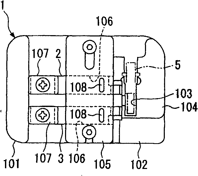
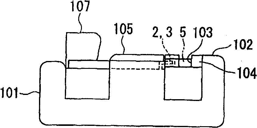
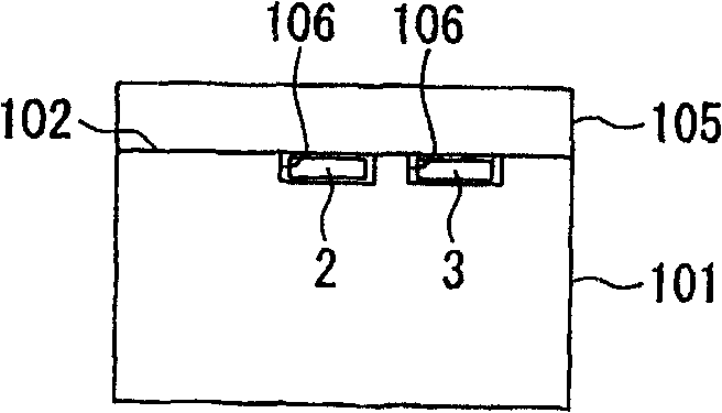
[0052] Figure 1 to Figure 15 Shown is the first embodiment of the optical fiber connecting tool of the present invention, and this optical fiber connecting tool 1 can be effectively applied to the situation that the optical fiber connecting part is installed on the front end part of the optical fiber, such as Figure 1A , B, it has a base 101 for fixing the optical fiber connection part 5 and two switch parts 2, 3 arranged on the base 101.

[0053] The optical fiber connection tool 1 of the present invention is applicable to various types of optical fiber connection components 5 .

[0054] Such as Figure 2A , B~shown in Figure 4, the optical fiber connection part 5 (hereinafter, there is also the situation that the optical fiber connecti...


PUM


Abstract

An optical fiber connection part (5), comprising a ferrule (7) and a connection mechanism (10) having two clamp parts (18) and (19), wherein an existing optical fiber (6) and a newly installed optical fiber (17) are clamped by one clamp part (18) in butt-jointed state and the other clamp part (19) clamps the newly installed optical fiber (7). An optical fiber connection tool (1), comprising two open / close members (2) and (3) operable independently of each other. An optical fiber connection method, comprising the step of, when fitting the optical fiber connection part (5) to the tip part of the newly installed optical fiber (17), after extracting one open / close member (2) from one clamp part (18), extracting the other open / close member (3) from the other clamp part (19), whereby a deflection caused at the butt-connected part of the optical fiber can be relieved to prevent a transmission loss from increasing and a damage to the optical fiber.

Description

field of invention [0001] The present invention relates to an optical fiber connection tool and an optical fiber connection method, in particular to an effective optical fiber connection tool for connecting an existing optical fiber on an optical fiber connection part and a new optical fiber separated from the existing optical fiber through a connection mechanism of the optical fiber connection part, and Fiber connection method. Background technique [0002] In recent years, regarding an optical fiber connector that can be easily installed on the front end portion of an optical fiber, the following has been disclosed: it has a ferrule in which an optical fiber is inserted in a central portion, and a connection provided on the end of the ferrule. mechanism. [0003] At this time, the connecting mechanism has: a two-split connecting element formed by combining two split parts, and a clamp spring (clamp spring) installed on the outside of the connecting element while applying ...

Claims


Application Information

Patent Timeline
Patent Type & Authority Patents(China)
IPC IPC(8): G02B6/24G02B6/36G02B6/38
CPCG02B6/3846G02B6/3652G02B6/3898G02B6/3636G02B6/3806G02B6/36G02B6/24
Inventor 齐藤大悟泷泽和宏
Owner FUJIKURA LTD
Learn More