
Ceramic bearing

A technology of ceramic bearings and ceramic materials, applied in the direction of bearing components, shafts and bearings, rigid supports of bearing components, etc., can solve the problems of short service life, unsatisfactory effect and high manufacturing cost of metal oil bearings, so as not to loosen and fall off , Overcoming the effect of easy breakage and not easy to shake

Inactive Publication Date: 2008-11-12
湖北锆源科技有限公司
View PDF3 Cites 0 Cited by
  • Summary
  • Abstract
  • Description
  • Claims
  • Application Information

AI Technical Summary

Problems solved by technology

Metal oil-impregnated bearings also have the disadvantages of short service life and easy vibration
Ball bearings have the advantage of long service life, but the manufacturing cost is very high, and the noise will increase significantly after long-term use, and the effect is not ideal

Method used


Image

  • Ceramic bearing
  • Ceramic bearing
  • Ceramic bearing

Examples


Embodiment Construction

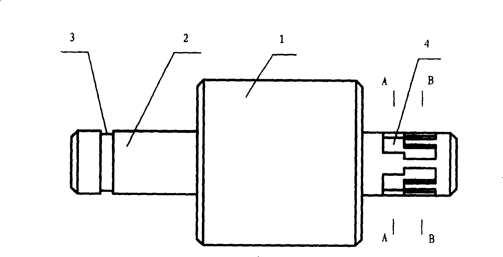
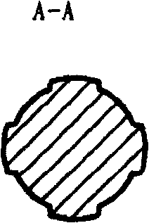
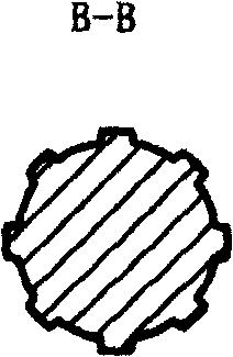
[0009] like figure 1 The shown ceramic bearing includes a shaft sleeve 1 and a shaft rod 2. The shaft sleeve 1 and the shaft rod 2 adopt a clearance fit. There are four grooves in one row, eight grooves in one row, and two rows of grooves are arranged in a staggered manner.

[0010] Both the shaft sleeve and the shaft rod are made of ceramic material, which is mainly composed of zirconia and has the characteristics of high hardness and wear resistance, so the invention has a long service life. There are two rows of vertical grooves on the tail of the shaft. The tail of the shaft is closely matched with the fan base. The shaft sleeve and the shaft adopt a clearance fit structure. The invention has the advantages of not being easy to vibrate and having low noise.

[0011] Figure 4 is another embodiment of the present invention. There is a row of vertical grooves at the end of the shaft.


PUM


Abstract

There is disclosed a ceramic bearing for miniature cooling fans, which includes a shaft sleeve and a shaft lever. The shaft sleeve and the shaft lever adopt a clearance fit. In the head part of the shaft lever is disposed a clasp slot and in the tail part of the shaft lever is opened a vertical groove. The shaft sleeve and the shaft lever are made of ceramic material consisting mainly of zirconium oxide, so they have advantages of high hardness and wear-resisting. The tail of the shaft lever is connected with the fan base.

Description

technical field [0001] The invention relates to a bearing, especially a ceramic bearing. Background technique [0002] At present, the bearings used in electronic cooling fans are mostly metal oil bearings or ball bearings. Metal oil-impregnated bearings include a shaft made of stainless steel and a shaft sleeve made of copper-iron-based metal. The dimensional accuracy of the stainless steel shaft needs to be extremely precise so that the shaft can be inserted into the sleeve smoothly. The surface of the shaft needs to be mirror-polished. In order to avoid wearing the lower hardness of the sleeve. Metal oil-impregnated bearings also have the disadvantages of short service life and easy vibration. The ball bearing has the advantage of long service life, but the manufacturing cost is very high, and the noise will obviously increase after long-term use, and the effect is not ideal. Contents of the invention [0003] The object of the present invention is to provide a ceram...

Claims


Application Information

Patent Timeline
Patent Type & Authority Patents(China)
IPC IPC(8): F16C35/10F04D29/056
Inventor 王俊冬
Owner 湖北锆源科技有限公司
Learn More