
CT open circuit protector with high sensitivity

An open-circuit protection and high-sensitivity technology, applied to emergency protection circuit devices, electrical components, etc., can solve problems such as low power frequency voltage threshold, control system confusion, personal casualties, etc., and achieve anti-interference ability to shield external electromagnetic fields, The effect of improved automation and strong anti-interference ability

Inactive Publication Date: 2008-10-29
靳建峰
View PDF4 Cites 0 Cited by
  • Summary
  • Abstract
  • Description
  • Claims
  • Application Information

AI Technical Summary

Problems solved by technology

The current transformer is a facility that can reflect the corresponding current parameters of the system for testing instruments and control facilities. The safe operation of the power system is very important. The operating regulations stipulate: ... During operation, the secondary side circuit of the current transformer CT cannot Once the circuit is opened, thousands or even tens of thousands of volts of high voltage will be generated, endangering the safety of staff, instruments and instruments, confusing the control system, causing large-scale power outages, seriously affecting the national economy and people's lives, and bringing great harm to industrial and agricultural production. serious economic losses and potential safety hazards, and even major accidents
The data shows that open circuits occur frequently, resulting in unnecessary equipment damage and personal casualties
[0003] In April 2004, the experimentally measured CT open circuit voltage was astonishingly high
At present, the signal measurement part of some protectors adopts rectification and filtering circuits, and the establishment of the signal voltage depends on time accumulation, which will inevitably prolong the start-up protection time and cannot implement protection in time.
[0014] (2) When it is in normal operation, it will affect the secondary measuring instrument and protection device. The voltage on the secondary side of CT is related to the impedance of the secondary side, the transformation ratio of CT and the size of the load. At present, some protection circuit input terminals have large The shunt effect, the secondary voltage decreases after being put into use, which makes the measurement of the instrument inaccurate, the sensitivity of the relay protection decreases, and the protection equipment does not act when protection is required
[0021] (3) The power frequency voltage threshold is not high, the anti-interference ability is poor, and the metering is reduced during normal work. When the system is short-circuited, it is equivalent to artificial blocking relay protection. The threshold of some protection circuits is based on the linear connection with the optical isolation input Resistor to achieve, linear resistance selection is not appropriate, will reduce sensitivity, low threshold
[0025] 2. The impedance of the secondary coil of the current transformer
[0036] It can be seen from the above data that even when the secondary side of the CT is normal, when the primary line of the power system is short-circuited, the secondary side of the CT will generate a voltage dozens of times higher than normal. Due to the low threshold value of the existing CT open circuit protection device, Make the CT open-circuit protection device act, artificially block the relay protection device, and the serious consequences will be unimaginable
In addition, the current secondary side open circuit protectors still have low sensitivity, large discrete technical performance, and unreliability; some CT open circuit protectors have harsh device requirements and are unrealistic; CT working status cannot be displayed, and operation is inconvenient; no communication Function, can not be connected with the integrated automatic control system of power transformation and distribution; high power consumption, waste of electric energy and other problems

Method used


Image

  • CT open circuit protector with high sensitivity
  • CT open circuit protector with high sensitivity
  • CT open circuit protector with high sensitivity

Examples


Embodiment 1

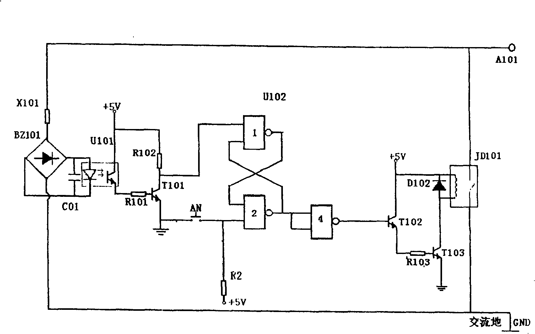
[0138] Embodiment one: see figure 1 , when the CT works normally, the input voltage of the secondary winding is low, the varistor X101 is disconnected, the rectifier bridge BZ101 has no output, the photoelectric isolator U01 has no current at the input diode, and the output has no output, T101 is cut off, T101 collector It is high potential, the output terminal of NAND gate 1 is at low potential, and the output terminal of NAND gate 2 is at high potential, which is sent to the driving circuit NAND gate 4 connected in parallel with the two input terminals, and the output of NAND gate 4 is low potential, T102, T103 is closed, and the normally open contact of JD101 connected in parallel with the CT secondary winding is still disconnected. When the secondary side of the CT is open, the output voltage of the secondary side of the CT is very high instantaneously, the piezoresistor X101 is in an instantaneous conduction state, the rectifier bridge BZ101 has an output, the input term...

Embodiment 2

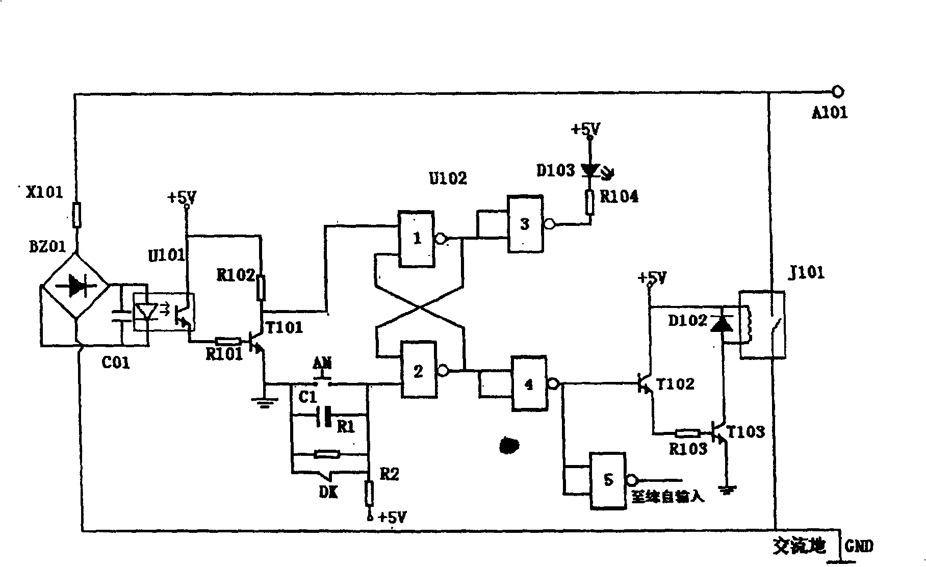
[0141] Embodiment two: see figure 2 , this embodiment has been improved on the basis of Embodiment 1. In this embodiment, the numbers that are the same as in Embodiment 1 represent the same components, and their working principles, states, and functions are the same, and will not be repeated. The different Yes: the output terminal of NAND gate 1 is connected to the input terminal of NAND gate 3, the two input terminals of NAND gate 3 are connected in parallel, the output terminal of NAND gate 3 is connected to the negative pole of light-emitting diode D103 through resistor R104, and the positive pole of D103 Connect +5V DC to form a display circuit. When CT is open circuit, NAND gate 1 outputs high potential, and NAND gate 3 outputs low potential, D103 has current to display the group and winding number of open circuit CT. The normally closed contact DK, capacitor C1, and resistor R1 of the circuit breaker at both ends of the button AN are connected in parallel, R1, R2, and ...

Embodiment 3

[0142] Embodiment three: see image 3 , this embodiment is improved on the basis of Embodiments 1 and 2. The numbers in the figure are the same as those of Embodiments 1 and 2, representing the same components, and their working principles, states, and functions are the same, and will not be repeated. The difference is: the output end of the NAND gate circuit 4 is connected with the input end of the NAND gate circuit 5 after the input terminal is connected in parallel, and the output end of the NAND gate circuit 5 is connected with the integrated automatic control system, which improves the automation of the present invention degree.


PUM


Abstract

The protecting apparatus is composed of the signal input sampling amplifying circuit the logic circuit, the execution protecting circuit. Through the sampling resistance, the voltage input is parallel connected with the input of the signal input amplifying circuit is connected with the input of the logic circuit, the output of the logic circuit is connected with the input of the execution protecting circuit.

Description

1. Technical field: [0001] The invention relates to a protection device for power lines, equipment, etc., in particular to a high-sensitivity CT open-circuit protection device. 2. Background technology: [0002] The safe operation of power lines is related to the national economy and the people's livelihood, as well as to the construction of the national economy and the safety of personnel. The current transformer is a facility that can reflect the corresponding current parameters of the system for testing instruments and control facilities. The safe operation of the power system is very important. The operating regulations stipulate: ... During operation, the secondary side circuit of the current transformer CT cannot Once the circuit is opened, thousands or even tens of thousands of volts of high voltage will be generated, endangering the safety of staff, instruments and instruments, confusing the control system, causing large-scale power outages, seriously affecting the n...

Claims


Application Information

Patent Timeline
Patent Type & Authority Patents(China)
IPC IPC(8): H02H7/00
Inventor 靳建峰
Owner 靳建峰
Learn More