Variable-frequency control dynamic head

A technology of variable frequency speed regulation and variable frequency speed governor, which is applied in the field of power head and can solve the problems of low output power of the motor and the like

Inactive Publication Date: 2008-10-08
陈硕
View PDF8 Cites 0 Cited by
  • Summary
  • Abstract
  • Description
  • Claims
  • Application Information

AI Technical Summary

Problems solved by technology

However, there is a defect that the motor output power is small at low speed

Method used


Image

  • Variable-frequency control dynamic head

Examples


Embodiment Construction

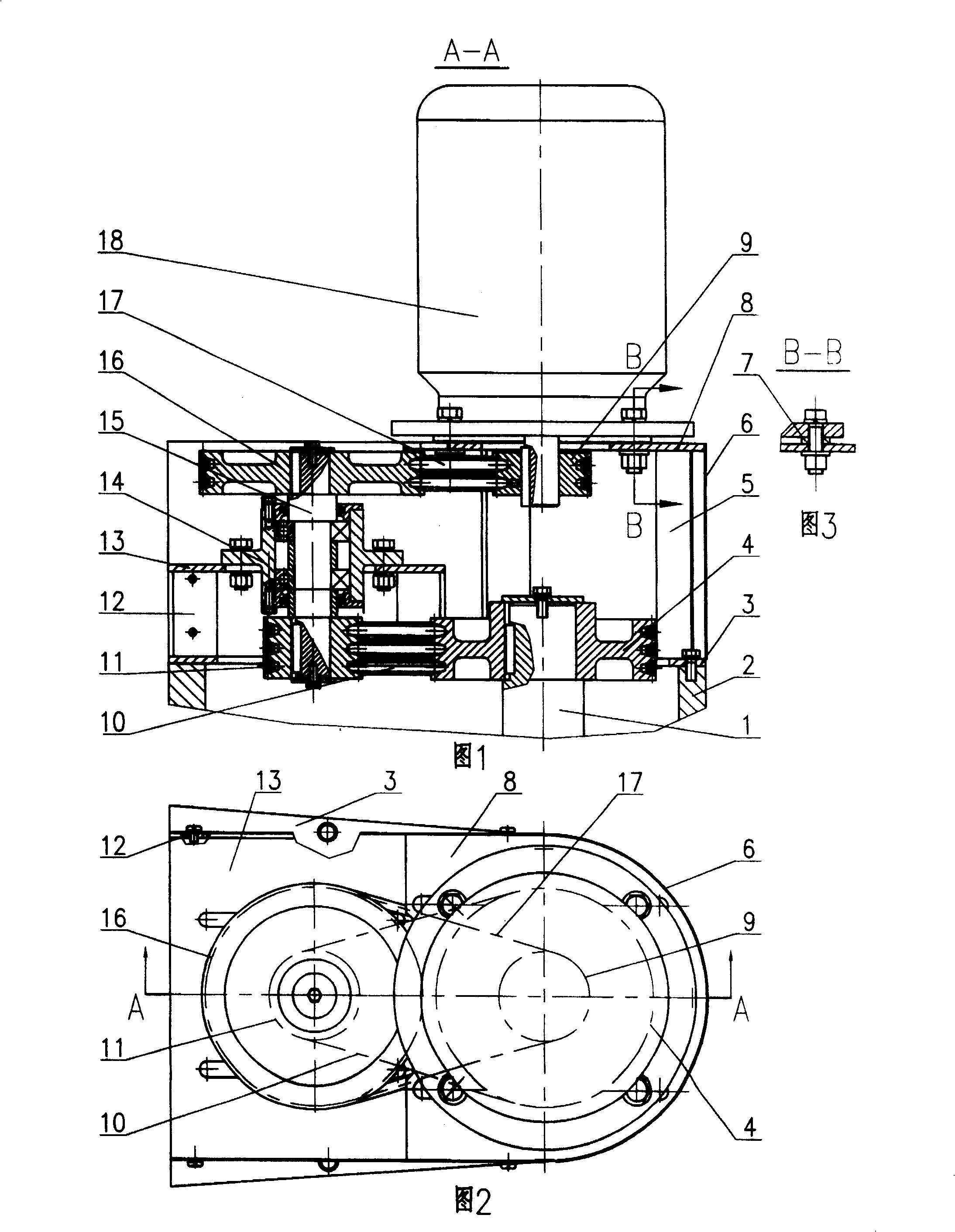
[0009] With reference to accompanying drawing, the decelerating mechanism that is contained on the support is fixed on the rear end of power head main shaft box body 2 with bolt by support bottom surface. Support is welded by support bottom plate 3, support long angle steel 5, support upper plate 8, support short angle steel 12, support middle partition 13. The profile of the support base plate 3 is consistent with the profile of the main shaft housing 2 rear ends, there is enough space for installing the main shaft pulley 4, the small pulley 11 and the main shaft belt 10 in the middle, and the partition plate 13 in the support is welded on with a plurality of support short angle steels 12 On the support base plate 3, the support upper plate 8 is welded on the support base plate 3 with many support long angle steels 5, the top of the partition plate 13 in the support, the top of the support upper plate 8 and the support base plate 3 bottom surfaces are parallel. There is a mid...


PUM


Abstract

The invention relates to a frequency-variable speed-adjust power head, which uses the motor controlled by frequency-variable speed adjuster, uses 2-step belt transmission speed reducer to transmit different speeds to the main axle of power head; said power head has stepless speed adjustment; the low-speed section has high power output; after 2-step speed reduction, the motor still has high rotation speed, when the main axle is low speed; therefore, the low-speed section has high power output; and the belt transmission can overcome impact, vibration and large noise, to improve the stability.

Description

Technical field [0001] The invention relates to machining equipment in machinery manufacturing, especially a power head. Background technique [0002] At present, the power head in the machining equipment is generally driven by the motor through the gear transmission structure to rotate the main shaft of the power head, and the speed of the main shaft of the power head is changed by changing the gear in the speed change mechanism. It is troublesome to change the speed, especially when the power head is working, the speed cannot be changed. Recently, the technology of motor speed regulation controlled by frequency converter has been widely used. Not only is the speed regulation very convenient, but also stepless speed regulation can be realized. However, there is a defect that the output power of the motor is small at low speeds. Contents of the invention [0003] The purpose of the present invention is to overcome the defects of the prior art and provide a variable frequ...

Claims


Application Information

Patent Timeline
Patent Type & Authority Patents(China)
IPC IPC(8): B23Q5/04H02K7/10
CPCY02P70/10
Inventor 陈硕
Owner 陈硕
Why Eureka
Try Eureka