
Two-freedom plane parallel high-speed high-accuracy robot

A degree of freedom, high-precision technology, applied in the direction of manipulators, manufacturing tools, etc., can solve problems such as unfavorable system speed, restricting system speed and acceleration, and reducing mechanism positioning accuracy.

Inactive Publication Date: 2008-10-01
HARBIN INST OF TECH +1
View PDF4 Cites 0 Cited by
  • Summary
  • Abstract
  • Description
  • Claims
  • Application Information

AI Technical Summary

Problems solved by technology

[0002] Existing high-speed, high-precision robot mechanisms have the following motion forms: (1) XYTable workbench mode: due to the heavy load of the motor on the base, the linear motion inertia is large, so the speed and acceleration of the system are restricted; in addition, the effective load of the system and The total load ratio is low, resulting in a large waste of electric energy
(2) Multi-joint parallel link mechanism driven by a rotating motor: the inertia of the multi-link mechanism is large, which is not conducive to further improvement of the system speed; at the same time, it also brings large deformation of the joint bearing, which reduces the positioning accuracy of the entire mechanism

Method used


Image

  • Two-freedom plane parallel high-speed high-accuracy robot
  • Two-freedom plane parallel high-speed high-accuracy robot

Examples


specific Embodiment approach 1

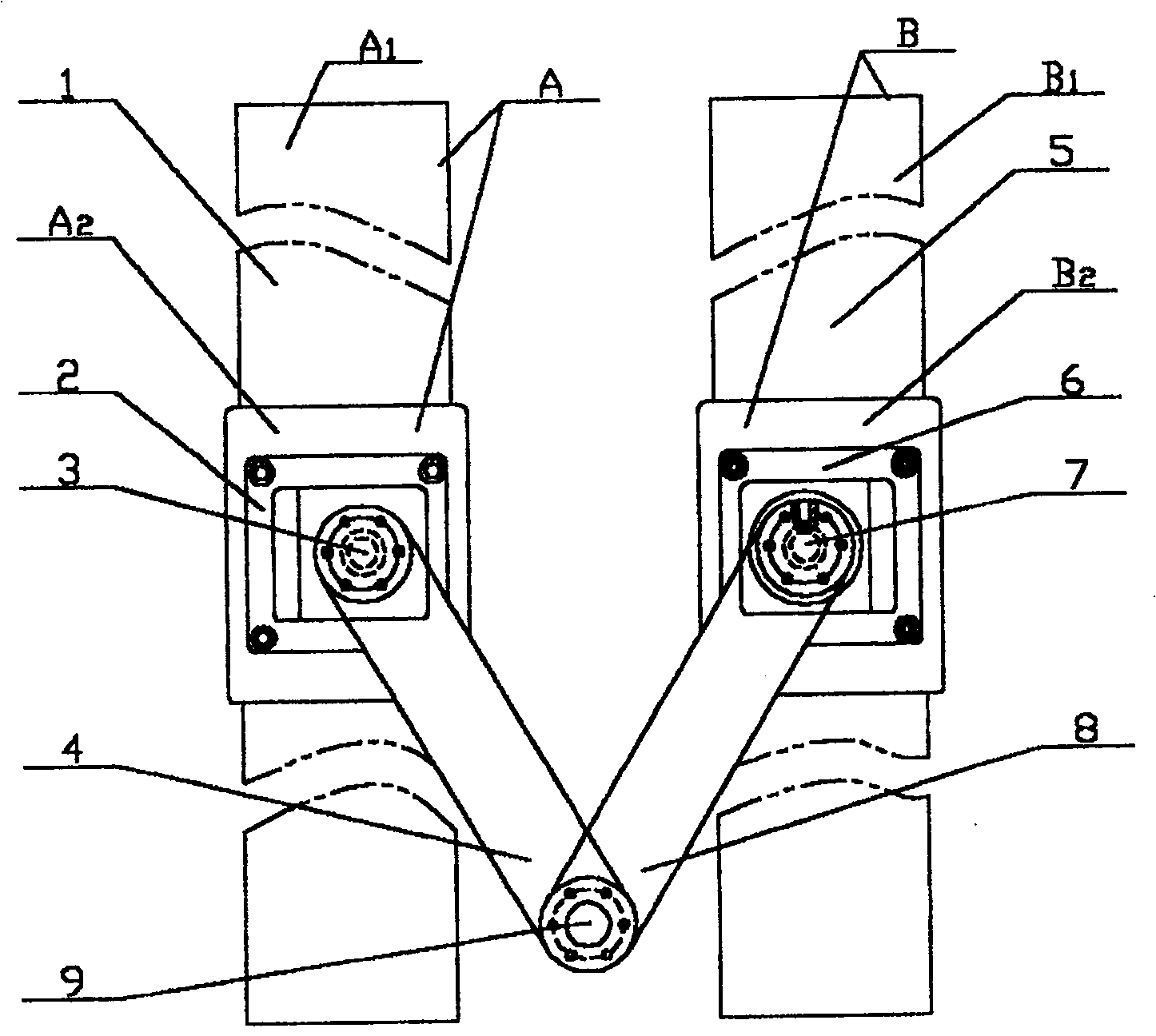
[0005] Specific implementation mode one: see figure 1 , the present embodiment is made up of left linear guide rail 1, right linear guide rail 5, left mobile platform 2, right mobile platform 6, driving device, left linkage 4, right linkage 8. The driving device is a left linear motor A and a right linear motor B arranged in parallel, and the stator guide rail A of the two linear motors 1 and B 1 That is, the left linear guide rail 1 and the right linear guide rail 5, the left moving platform 2 and the right moving platform 6 are respectively fixedly connected to the mover A of the two linear motors 2 and B 2 On; one end of the left link 4 and the right link 8 is connected with the left moving platform 2 and the right moving platform 6 through the first turning pair 3 and the second turning pair 7 respectively, and the other end of the left link 4 and the right link 8 One end is connected to each other through the end rotating pair 9.

specific Embodiment approach 2

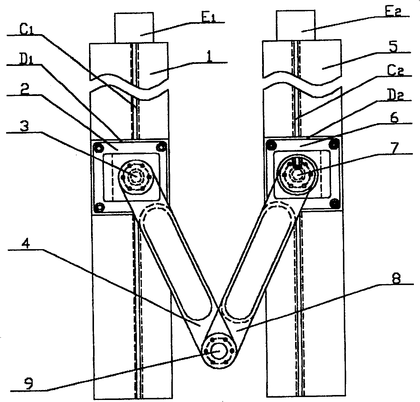
[0006] Specific implementation mode two: refer to figure 2 The difference between this embodiment and the first embodiment is that the driving device consists of a left lead screw C arranged on the left linear guide rail 1 and the right linear guide rail 5 1 and right lead screw C 2 , the left slider D matched with the left and right screw respectively 1 and right slider D 2 , the left motor E that drives the left and right lead screws to rotate 1 and right motor E 2 composition, the left mobile platform 2 and the right mobile platform 6 are respectively installed on the left slider D 1 and right slider D 2 superior. In this embodiment, the motor drives the lead screw to rotate, and the left and right platforms generate linear motion through the slider, and the linear motion of the platform is converted into a two-dimensional plane motion at the end of the link. Other compositions and connections are the same as in the first embodiment.


PUM


Abstract

The present invention relates to a kind of industrial robot, in particular, it relates to a two-freedom plane-moved robot. It includes mutually parallelly-arranged left straight-line guideway and right straight-line guideway, left moving platform and right moving platform which are respectively arranged on the left straight-line guideway and right straight-line guideway and can make straight-line movement along the guideway, drive device for driving left moving platform and right moving platform and left link and right link, one end of left tank and right link can be respectively connected with left moving platform and right moving platform by means of first turning pair and second turning pair, and their another ends are mutually connected by means of tail end turning pair.

Description

technical field [0001] The invention relates to an industrial robot, in particular to a two-degree-of-freedom plane moving robot. Background technique [0002] Existing high-speed, high-precision robot mechanisms have the following motion forms: (1) XYTable workbench mode: due to the heavy load of the motor on the base, the linear motion inertia is large, so the speed and acceleration of the system are restricted; in addition, the effective load of the system and The total load ratio is low, resulting in a large waste of electric energy. (2) Multi-joint parallel linkage mechanism driven by a rotating motor: the inertia of the multi-link mechanism is large, which is not conducive to further improvement of the system speed; at the same time, it also brings large deformation of the joint bearing, which reduces the positioning accuracy of the entire mechanism. Contents of the invention [0003] In order to solve the problems existing in the prior art, the present invention pr...

Claims


Application Information

Patent Timeline
IPC IPC(8): B25J5/02
Inventor 孙立宁曲东升楚中毅
Owner HARBIN INST OF TECH
Learn More