Full electrodynamic mould locking device of rubber injection machine

A technology of a clamping device and an injection machine, which is applied in the field of all-electric clamping devices for rubber injection machines, can solve the problems of a clamping device that is not suitable for a large stroke, affects reliability, and has high operating costs, and saves space and floor space. , The effect of improving the fixed force condition and improving the transmission efficiency

Inactive Publication Date: 2008-08-27
QINGDAO UNIV OF SCI & TECH
View PDF4 Cites 0 Cited by
  • Summary
  • Abstract
  • Description
  • Claims
  • Application Information

AI Technical Summary

Problems solved by technology

The mechanical clamping device has the following disadvantages: (1) The mechanical structure is complex and bulky; (2) It is not suitable for large-stroke clamping devices
The hydraulic clamping device has the following disadvantages: (1) waste of energy. During the entire operation process, the motor is always in working condition, resulting in waste of electric energy. At the same time, during the operation process, the electric energy is converted into hydraulic energy and then converted (2) In the hydraulic system, there are too many wearing parts, which can easily lead to mechanical failure and affect reliability; (3) During the operation, the hydraulic system is prone to leakage, which deteriorates the working environment; (4) Difficult to maintain and high operating costs
The mechanical hydraulic clamping device also has the above disadvantages

Method used


Image

  • Full electrodynamic mould locking device of rubber injection machine
  • Full electrodynamic mould locking device of rubber injection machine
  • Full electrodynamic mould locking device of rubber injection machine

Examples


Embodiment Construction

[0024] The present invention will be further described below in conjunction with the accompanying drawings and embodiments, which are not intended to limit the present invention.

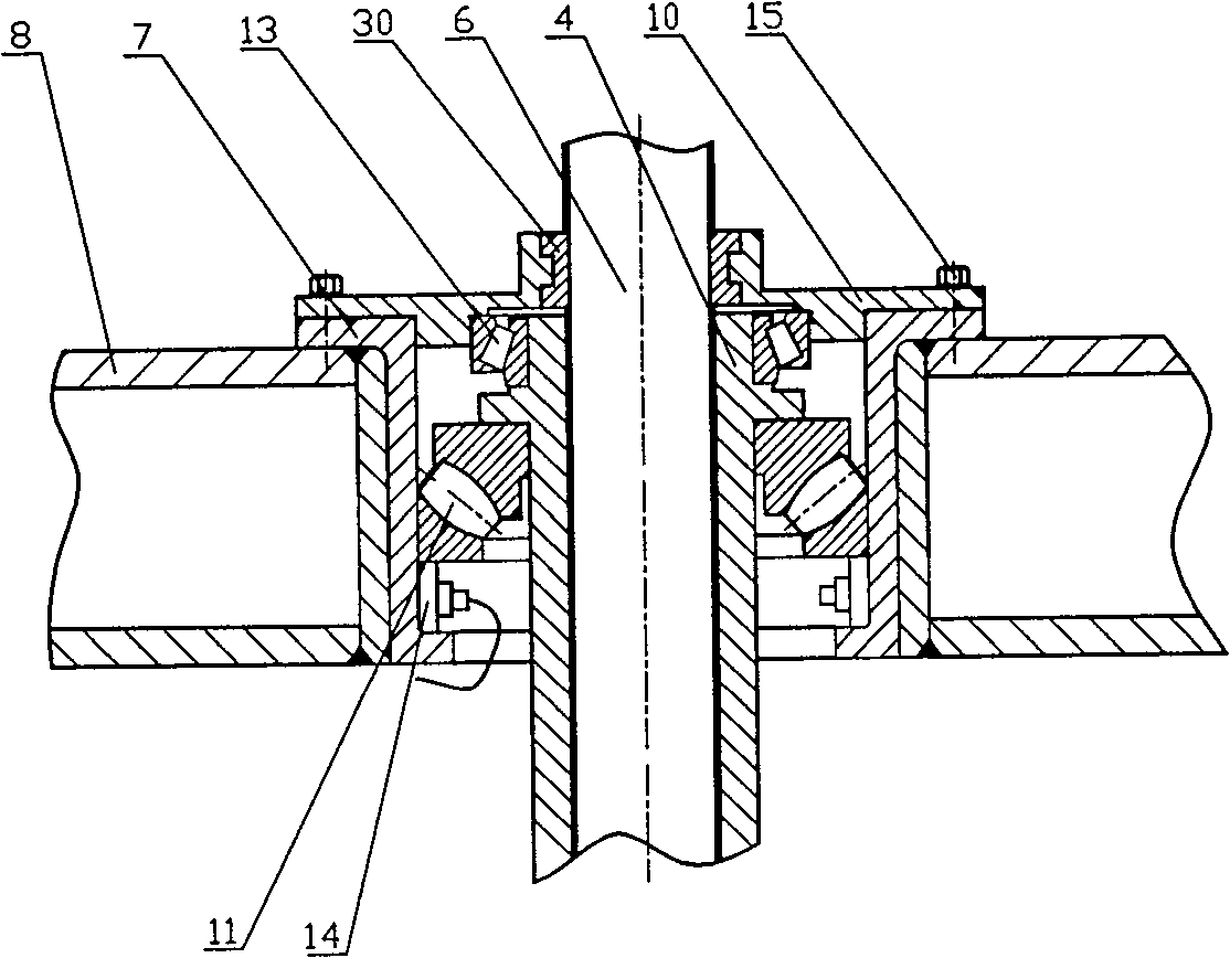
[0025] figure 1 It is a schematic diagram of the general structure principle of the all-electric mold clamping device of the rubber injection machine of the present invention. Including electric screw transmission system, bearing box and electric demoulding part. In the electric screw transmission system, there is a planar double-enveloping worm gear reducer 1, and a two-speed motor 2 with high starting torque is installed at the input shaft end of the reducer 1, and the output spindle of the reducer 1 is a hollow shaft 3, A drive nut 4 is installed in the inner hole, and the drive nut 4 is connected with the hollow shaft 3 with a flat key 5, and a main screw 6 is assembled in the center of the nut 4 . The ball head end of the main screw 6 cooperates with the ball head seat 9 installed on the bott...


PUM


Abstract

A full-electric mould locking unit for rubber injector is composed of an electric screw drive system consising of speed reducer and dual-speed motor, a bearing case and an eelctric demoulding unit. A main scrwe connected with the movable mould plate is engaged with a long cylindrical drive nut in the inner hole of a hollow output shaft of speed reducer for locking or opening the mould.

Description

technical field [0001] The invention relates to the field of rubber injection molding processing machinery, in particular to an all-electric mold clamping device for a rubber injection machine. Background technique [0002] At present, the clamping devices of rubber injection machines at home and abroad mainly have three structural forms, one is the mechanical toggle type, the other is the mechanical hydraulic type, and the third is the hydraulic type. The mechanical clamping device has the following disadvantages: (1) the mechanical structure is complex and bulky; (2) the clamping device with a large stroke is not suitable. The hydraulic clamping device has the following disadvantages: (1) waste of energy. During the entire operation process, the motor is always in working condition, resulting in waste of electric energy. At the same time, during the operation process, the electric energy is converted into hydraulic energy and then converted (2) In the hydraulic system, th...

Claims


Application Information

Patent Timeline
Patent Type & Authority Patents(China)
IPC IPC(8): B29C45/66
Inventor 吕柏源危卫华
Owner QINGDAO UNIV OF SCI & TECH
Why Eureka
Try Eureka