Cylinder block for a water-cooled internal combustion engine

A technology for cylinder blocks and internal combustion engines, which is applied in the direction of engine cooling, cylinders, cylinder heads, etc., and can solve problems affecting the flow of cooling jackets, etc.

Inactive Publication Date: 2008-08-06
AVL LIST GMBH
View PDF4 Cites 0 Cited by
  • Summary
  • Abstract
  • Description
  • Claims
  • Application Information

AI Technical Summary

Problems solved by technology

[0003] It is obviously not possible to additionally influence the flow in the cooling jacket to a sufficient extent with known flow restrictors

Method used


Image

  • Cylinder block for a water-cooled internal combustion engine
  • Cylinder block for a water-cooled internal combustion engine

Examples


Embodiment Construction

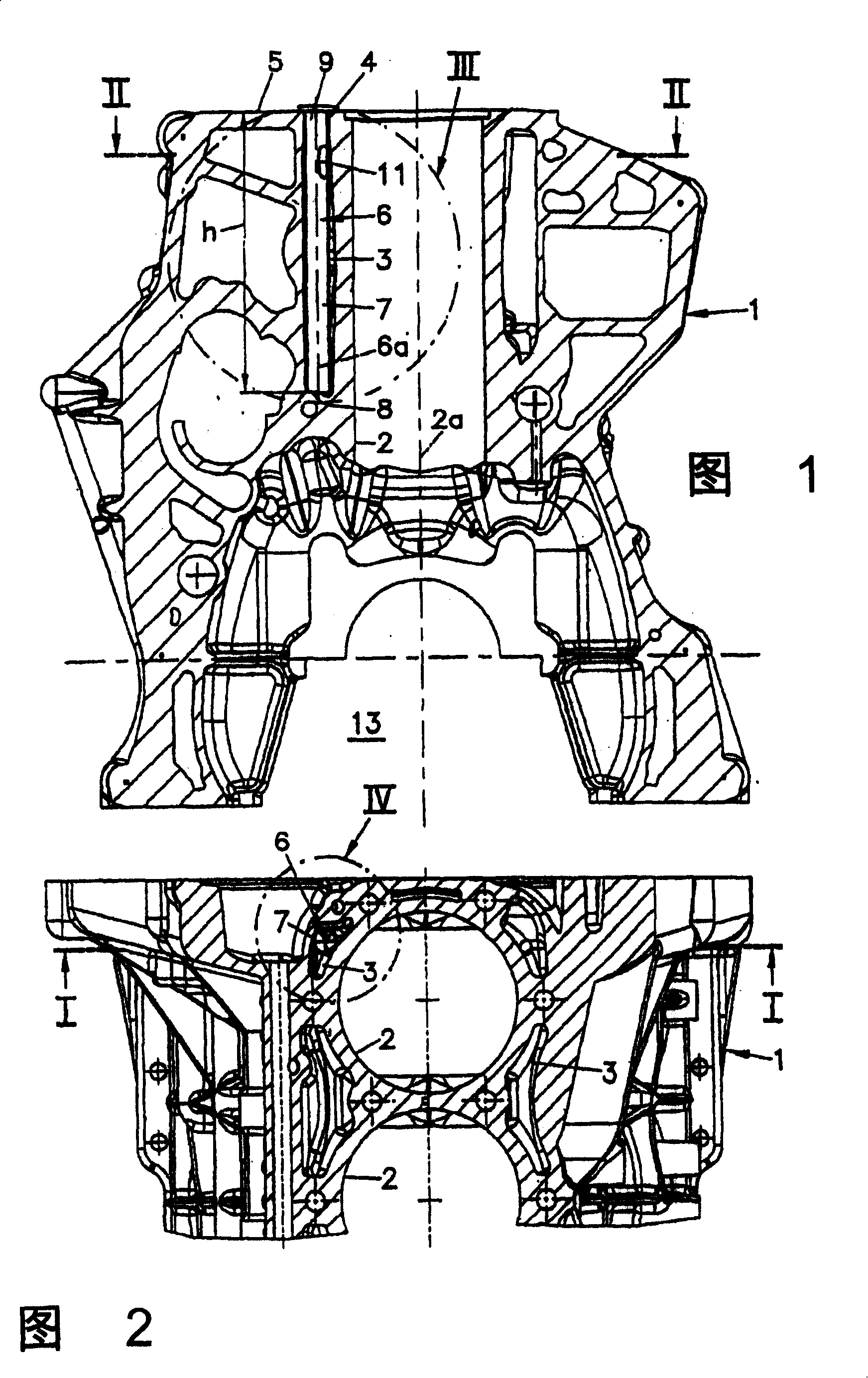
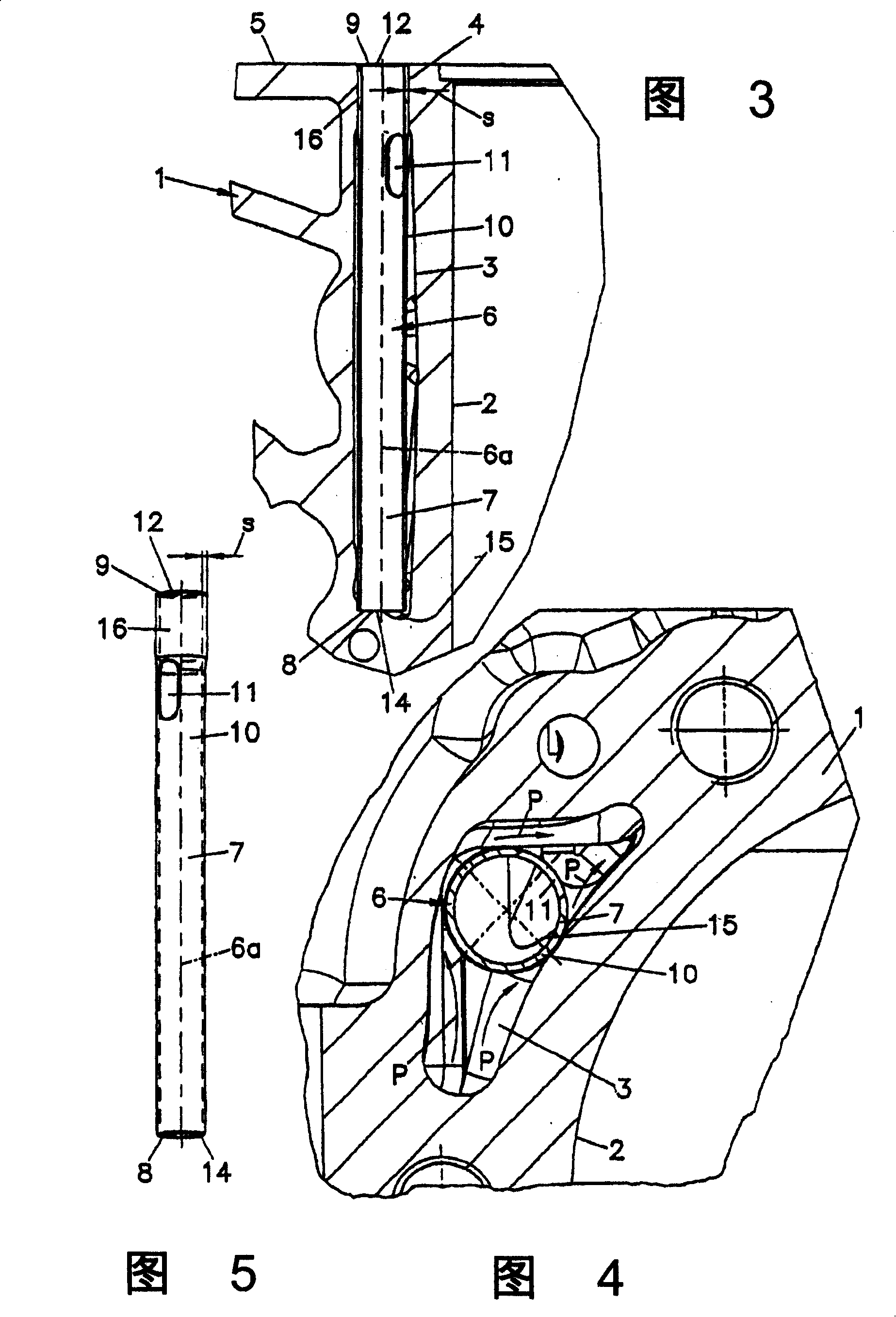
[0019] The cylinder block 1 of the internal combustion engine shown in FIGS. 1 to 4 has a cylinder 2 for a plurality of pistons (not shown). The cylinder block 1 may be constructed separately from or integrally formed with the crankcase. A cooling jacket 3 is arranged around the space of the cylinder 2 . The cooling jacket 3 is connected to the cooling space of the cylinder head via transition openings 4 in a connection surface 5 for the cylinder head (not shown). A flow limiter 6 is inserted into the transition opening 4 of at least one outer cylinder 2 of the cylinder bank. The flow limiter 6 essentially consists of a tube 7 with open end faces 8 , 9 , wherein a third inlet 11 is provided on the outer surface of the tube 7 on the side of the cylinder head. The outlet on the end face 9 facing the cylinder head is denoted by reference "12". The longitudinal axis 6a of the flow restrictor 6 extends approximately parallel to the cylinder axis 2a.

[0020] The length of the p...


PUM


Abstract

The invention relates to a cylinder block for a water-cooled internal combustion engine. Said block comprises at least one cylinder that is surrounded by a cooling jacket and a connection surface for a cylinder head, which has at least one overflow opening for the passage of coolant from the cooling jacket into the cylinder head. To achieve the uniform cooling of the cylinder block and the cylinder head, a flow restrictor is inserted into the overflow opening.

Description

technical field [0001] The invention relates to a cylinder block for a water-cooled internal combustion engine with at least one cylinder surrounded by a cooling jacket, with a connecting surface for a cylinder head comprising at least one cylinder for the flow of coolant from the cooling jacket Transition openings (Ubertrittsoffnung) into the cylinder head. Background technique [0002] It is known that the flow of coolant between the engine block and the cylinder head is deliberately influenced by the different dimensions of the transition openings in the cylinder head gasket. Furthermore, it is known from EP 0368519 A2 to insert a flow restrictor in the inflow or return line of the cooling circuit. [0003] It is obviously not possible to additionally influence the flow in the cooling jacket to a sufficient extent with known flow restrictors. Contents of the invention [0004] In view of the above-mentioned deficiencies existing in the prior art, the object of the pre...

Claims


Application Information

Patent Timeline
IPC IPC(8): F02F1/42F02F1/14F01P3/02F02F7/00
CPCF01P2003/021F02F7/007F02F1/14F01P3/02
Inventor R·安赞道弗
Owner AVL LIST GMBH
Why Eureka
Try Eureka