DC brushless oscillating motor

A vibrating motor and DC brushless technology, which is applied in the direction of electric components, mechanical energy control, electrical components, etc., can solve the problems of large eccentricity between the ring magnet and the rotation center, the inability to realize the miniaturization design of the motor, and increase the input power. Small number, reduced winding complexity, and the effect of reducing the number of motor parts

Inactive Publication Date: 2008-06-25
RISUN EXPANSE
View PDF12 Cites 0 Cited by
  • Summary
  • Abstract
  • Description
  • Claims
  • Application Information

AI Technical Summary

Problems solved by technology

However, this method will increase the load of the rotor and increase the input electric energy, and because the load block is installed in addition, the volume of the overall motor will increase, and the miniaturization design of the motor cannot be realized; The means of vibration is to use the coplanar four-pole ring magnet to be eccentrically arranged on the rotor disk, and then let the rotor disk rotate. Since the center of gravity of the rotor deviates from the rotation center, vibration can be generated. However, due to space constraints, the ring magnet and the rotation The amount of eccentricity of the center cannot be too large, thus limiting the increase in the amount of vibration

Method used


Image

  • DC brushless oscillating motor
  • DC brushless oscillating motor
  • DC brushless oscillating motor

Examples


Embodiment Construction

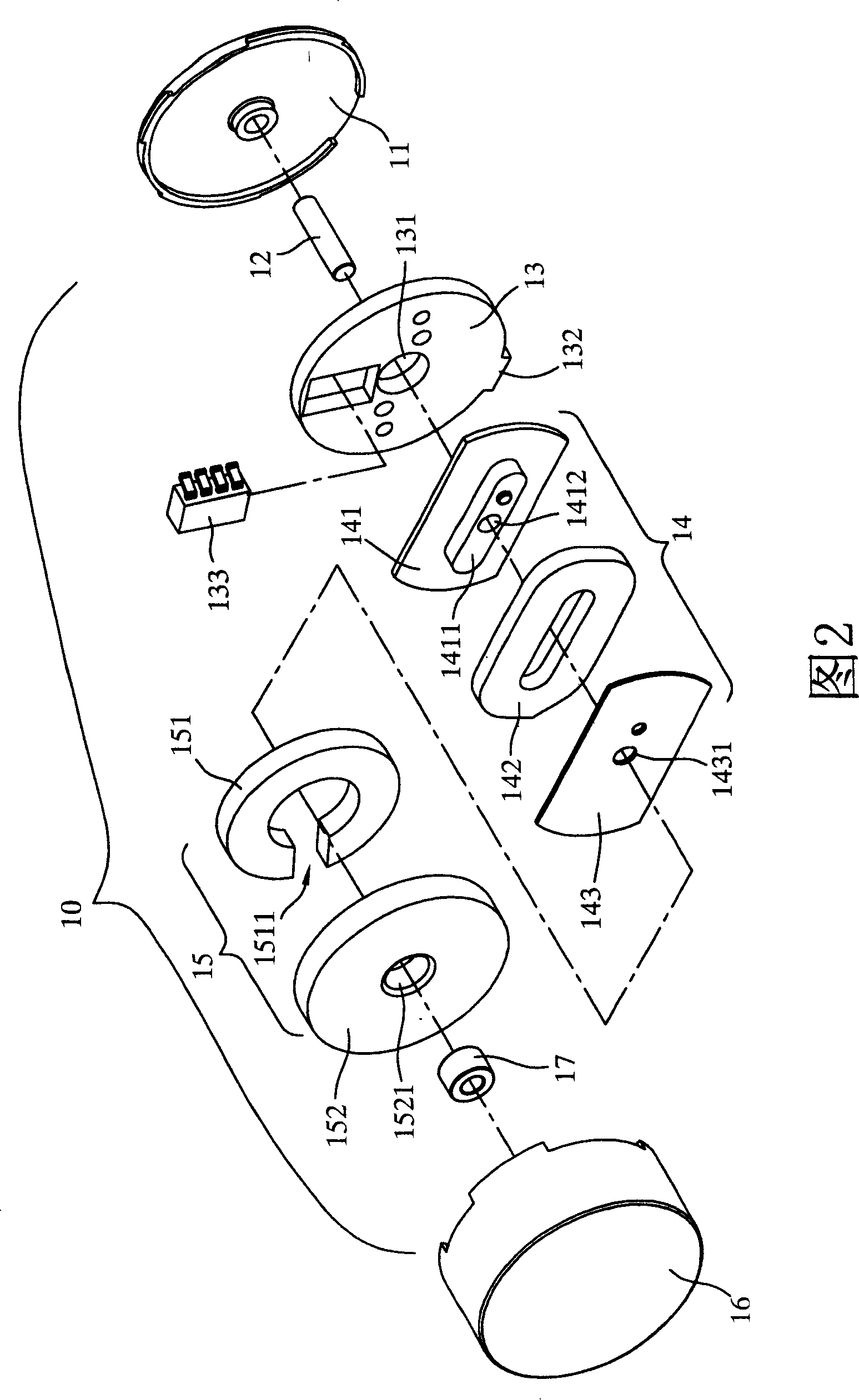
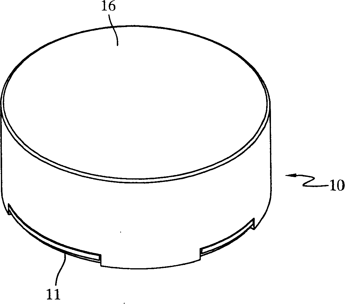
[0031] Please refer to Figure 2~ Figure 4 As shown, according to the brushless DC vibration motor 10 disclosed in the present invention, it includes a chassis 11, a shaft 12, a circuit board 13, a winding group 14, a rotating device 15 and a casing 16; wherein the chassis 11 It is in the shape of a disc, and the shell 16 is in the shape of a hollow cylinder. The shell 16 can be combined with the chassis 11 to form the appearance of a flat cylindrical brushless DC vibration motor 10, and can accommodate the axis 12 and the circuit board. 13. The winding group 14 and the rotating device 15 are contained therein.

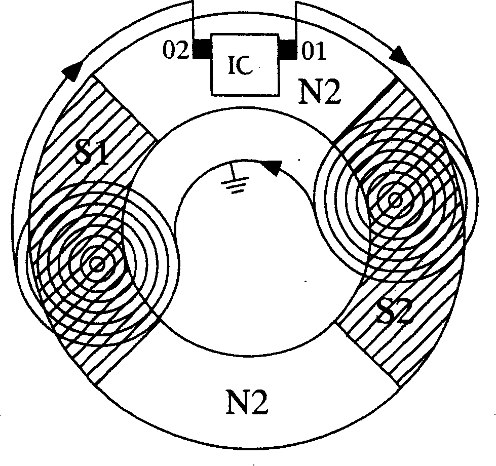
[0032] The axis 12 is set at the center of the chassis 11 and defines the rotation center of the brushless DC vibration motor 10. The circuit board 13 is circular and has a perforation 131 in the center to be sleeved on the axis 12 and set on the chassis 11. Above, a power input port 132 is provided on the circuit board 13 to be electrically connected with an externa...


PUM


Abstract

This invention relates to a DC brushless vibration motor, which takes a sensing coil and magnetic appliances with multiple share plane magnetic poles as the stator and rotor of a motor, in which, the sensing coil is winded to a ring by a single lead and the winding sphere is corresponding to the two opposite same polarity magnetic poles, a centrifugal slot is set on the magnetic device to deviate the gravity center from the axes, when the current is input to the sensing coil to form a magnetic field, it makes the device and the field generated by the sensing coil to exclude each other to rotate and vibration force is generated since the gravity center of the device deviates from the axes.

Description

technical field [0001] The invention relates to a DC brushless vibration motor, in particular to a DC brushless vibration motor which uses a single wire wound to form an induction coil as a rotor, and generates vibration kinetic energy by changing the center of gravity of a magnetic device. Background technique [0002] For example, U.S. Patent No. 6700275 and U.S. Patent No. 6850019, both adopt the method of winding a single wire into multiple coils, and utilize the principle that adjacent coils have opposite winding directions and produce opposite magnetic poles after the coils are energized. Such coils The structure is still single-wire multipole. But in the winding process, after winding a coil, the winding machine must suspend the winding action, then turn the next winding post to enter the winding position, and then perform winding in the opposite direction, and repeat this many times. Therefore, this winding method will undoubtedly increase the complexity of the desi...

Claims


Application Information

Patent Timeline
Patent Type & Authority Patents(China)
IPC IPC(8): H02K7/06H02K29/08
Inventor 黄江城张钧闵孙建中
Owner RISUN EXPANSE
Why Eureka
Try Eureka