Eureka AIR delivers breakthrough ideas for toughest innovation challenges, trusted by R&D personnel around the world.

Optical transmission network protection method

A technology of optical transmission network and protection group, which is applied in the field of communication, and can solve problems such as no business operation, business interruption, and inconsistent status of the protection domain

Inactive Publication Date: 2008-06-18
HUAWEI TECH CO LTD
View PDF3 Cites 2 Cited by
  • Summary
  • Abstract
  • Description
  • Claims
  • Application Information

AI Technical Summary

Problems solved by technology

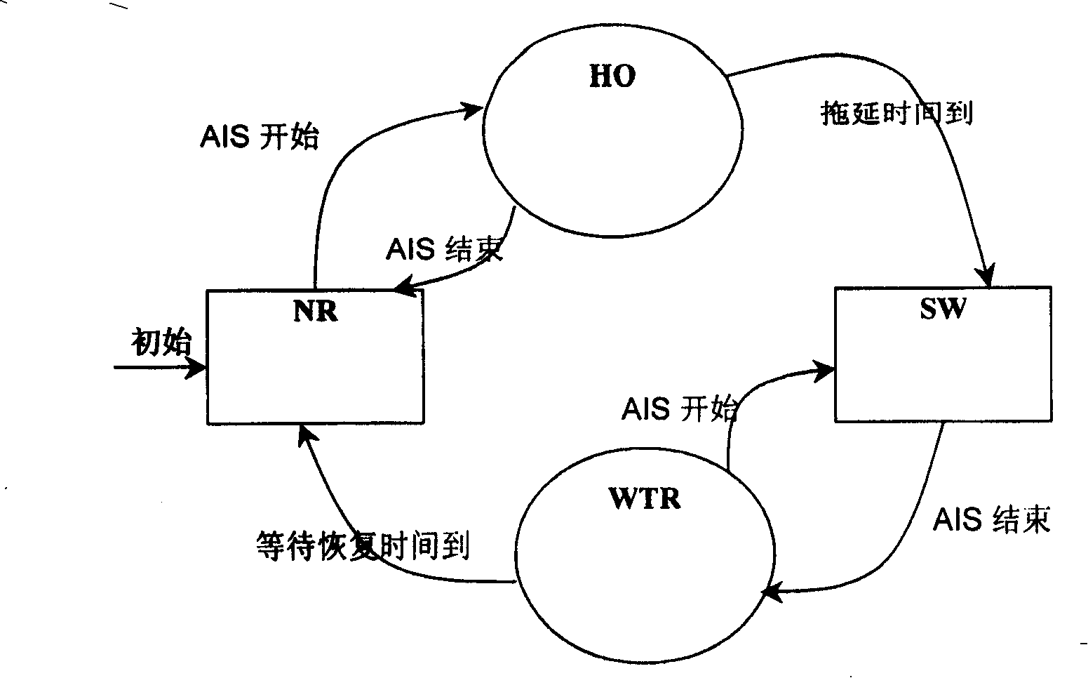
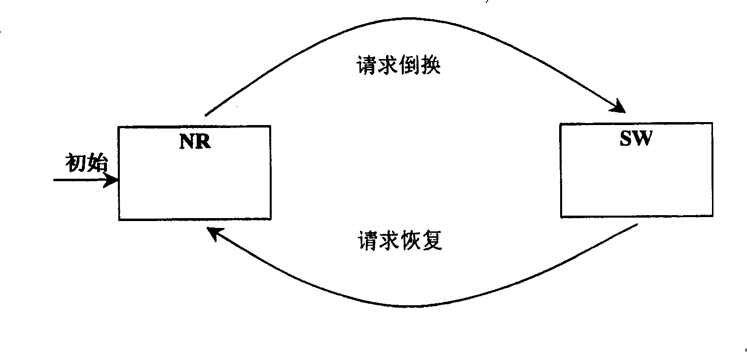
[0018] In the case of 1+1 active / standby boards, the working connection and protection connection of the standby board do not actually run services, and the state machine of the backup protection group on the standby board is difficult to synchronize with the state machine of the main board, and the state machine of the protection group on the standby board is in NR status; after a single board 1+1 active / standby switchover occurs, the service is switched to the working connection on the standby board, and if the service has been switched at this time, the status of both sides of the protection domain will be inconsistent and cause long-term service interruption

Method used


Image

  • Optical transmission network protection method
  • Optical transmission network protection method
  • Optical transmission network protection method

Examples


Embodiment Construction

[0040] The specific implementation manners of the present invention will be described below in conjunction with the accompanying drawings.

[0041] This embodiment uses ATM as an example for introduction, and the multiplex section protection of the synchronous digital series is handled similarly.

[0042] The processing mode of the ATM service protection switching group in the optical transmission network is as follows: Figure 3a , 3b , 3c, the 1:1 one-way is taken as an example in these figures, and the reverse path only shows the part of sending APS information.

[0043] The active-end network element and the passive-end network element perform state synchronization through the K1 and K2 bytes of the APS information. The active network element detects the conditions of automatic switching, and when it detects that the signal disappears (LCD) or the service is faulty (AIS), the following operations are performed:

[0044] S1: The active network element switches to the pro...


PUM


Abstract

The invention relates to a method for protecting the optical transmission network, which is characterized in following steps: a, initializing the network unit protection group; b, judging if it is the initialization of normal recovery of network unit protection group, if it is, turning to the step c, or else, turning to the step d; c, entering into the normal state of network protection group state machine; d, according to the request information of opposite to the network unit protection group, entering relative state of state machine. The invention via extending the protection reverse protocol state machine, can effectively avoid the service interruption caused by the asynchronous protocol state machines at the two ends of protection field caused by the recovery or single plate reverse of network software and hardware at one end or two ends of protection field which is in reverse state.

Description

technical field [0001] The invention relates to the communication field, in particular to a method for protecting an optical transmission network. technical background [0002] As stipulated in international standards, APS (Auto Protection Switching) protection of optical transmission network elements is realized through protection groups and their protection protocols, such as multiplex section protection of synchronous digital hierarchy (SDH) and VP of asynchronous transfer mode (ATM) Ring. The principles of SDH linear multiplex section protection and ATM VP Ring are basically the same. The main difference is that the information definitions of K1 and K2 protocol bytes are different. K1 and K2 are carried in APS cells. The following uses an ATM as an example for introduction. [0003] ATM services are divided into virtual path (VP Virtual Path) connection and virtual channel (VCVirtual Channel) connection on the transmission network, and corresponding service protection...

Claims


Application Information

Patent Timeline
Patent Type & Authority Patents(China)
IPC IPC(8): H04L12/437
Inventor 李喜祥
Owner HUAWEI TECH CO LTD
Why Eureka
Eureka Blog
Learn More