Pump-adjuster of braker with pressure-releasing valve

A technology of brake wheel cylinder and pressure relief valve, which can be used in brakes, vehicle maintenance, manufacturing tools, etc., and can solve problems such as inconvenient maintenance.

Inactive Publication Date: 2008-06-18
COSDA MANU FACTURING
View PDF7 Cites 0 Cited by
  • Summary
  • Abstract
  • Description
  • Claims
  • Application Information

AI Technical Summary

Problems solved by technology

[0005] The technical problem to be solved by the brake cylinder regulator with a pressure relief valve in the present invention is that the rotation of the screw of the known cylinder regulator must consider the rotation direction of the screw teeth of the cylinder for corresponding use, so maintenance personnel need to At the same time, two kinds of screw rotation directions are prepared for use together, which is more inconvenient for maintenance.

Method used


Image

  • Pump-adjuster of braker with pressure-releasing valve
  • Pump-adjuster of braker with pressure-releasing valve
  • Pump-adjuster of braker with pressure-releasing valve

Examples


Embodiment Construction

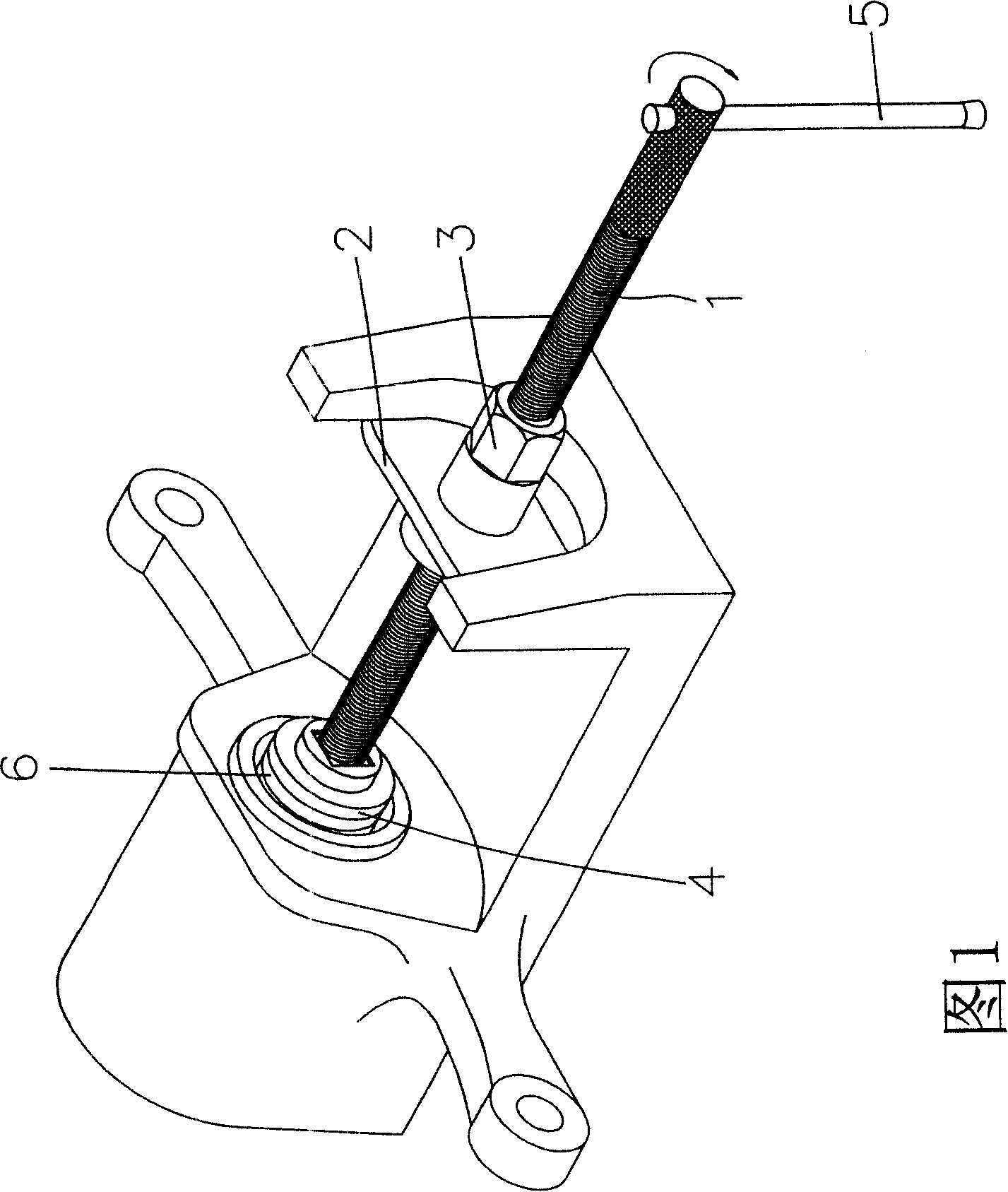
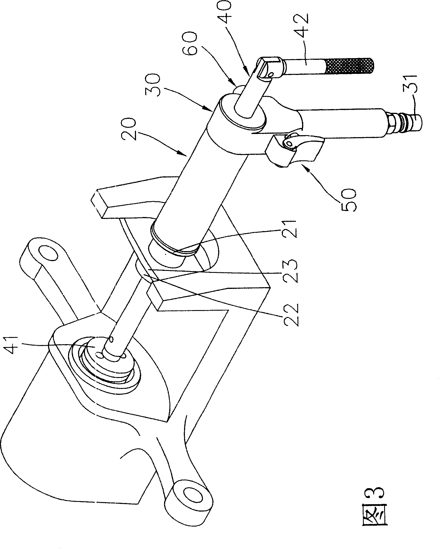
[0019] Referring to FIG. 3 , a perspective view of the present invention. It is shown that the present invention includes a cylinder body 20, which has a first end and a second end, and the first end has a first fixing part 21 and a second fixing part 22 combined therewith, and the first fixing part 21 and the second fixing part 22 is interrotated with a fixed piece 23 .

[0020] A handle 30 is fixed at the second end of the cylinder body 20 at one end. The other end is provided with a joint 31 to connect with the air pressure source.

[0021] A push rod 40 movably passes through the cylinder body 20 and the handle 30 . One end of the push rod 40 is provided with a resisting plate 41 for pressing the cylinder, and the other end is provided with a handle 42 for rotating the push rod 40 .

[0022] An intake valve 50 is disposed on one side of the handle 30 to control whether the air pressure enters the cylinder 20 or not.

[0023] A pressure relief valve 60 is disposed on the...


PUM


Abstract

A brake subpump adjuster with a pressure-relief valve comprises a cylinder, a lever, a push rod, an intake valve and a pressure-relief valve. The cylinder has first and second ends and at the first end is disposed a fixed piece. One end of the lever is set at the second end of the cylinder and the other end has a joint. The push-rod movable passes through the cylinder and the handle. At one end of the push-rod is disposed a support piece to press the subpump and at the other end is disposed a handle to rotate the push-rod. The intake valve is disposed on one side of the lever to make the piston move, so as to make the push-rod shift. The pressure-relief valve is set on the other side of the lever for relasing high-pressure gas from the cylinder to pull back the push-rod to the initial position.

Description

technical field [0001] The invention mainly discloses a brake cylinder regulator, in particular, a brake cylinder regulator with a pressure relief valve. Background technique [0002] At present, the brake cylinder of automobiles will gradually protrude as the brake pads wear and become thinner. When the brake pads are worn to a certain extent and must be replaced, the cylinder shaft must be rotated and pressurized to return to the original distance. Replace with new brake pads. [0003] However, the structure of the traditional sub-pump adjuster (as shown in Figure 1 and Figure 2) approximately includes a screw rod 1, 1a, one end of which is provided with a handle 5, the other end is provided with a resisting piece 4, a fixing piece 2, and a There is a nut 3 on the side to allow the screw 1 to pass through, so as to achieve the effect of pressing the sub-pump 6 in. However, the general disc brake sub-cylinder is shared with the hand brake, and some sub-cylinders use right...

Claims


Application Information

Patent Timeline
Patent Type & Authority Patents(China)
IPC IPC(8): B25B27/00B23P19/04B60S5/00B60T17/00
Inventor 刘来诚
Owner COSDA MANU FACTURING
Why Eureka
Try Eureka