
Charging device and imaging device using same

A charging device and image technology, applied to corona discharge devices, equipment for electric recording technology using charge patterns, and electric recording technology using charge patterns, etc., can solve the problems of large hazards and increased size of imaging devices

Inactive Publication Date: 2008-06-04
FUJIFILM BUSINESS INNOVATION CORP
View PDF9 Cites 0 Cited by
  • Summary
  • Abstract
  • Description
  • Claims
  • Application Information

AI Technical Summary

Problems solved by technology

When a cleaner is provided for the photoconductive drum, if the capacity of the collection box of the waste toner collected by the cleaner is set larger, the size of the image forming device itself will increase
Especially in so-called tandem full-color copiers with photoconductive drums for each color of yellow, magenta, cyan, and black, the hazard is greater

Method used


Image

  • Charging device and imaging device using same
  • Charging device and imaging device using same
  • Charging device and imaging device using same

Examples


Embodiment Construction

[0028] A charging device according to the present invention and an image forming device using the charging device will be discussed below with reference to the accompanying drawings.

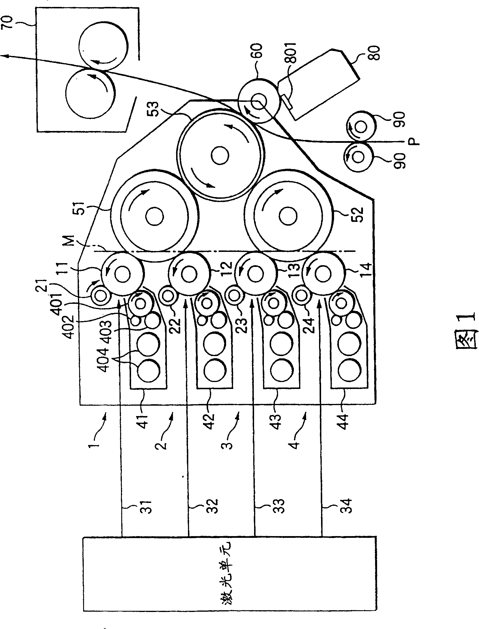
[0029] FIG. 1 shows a full-color laser beam printer including a charging device according to the present invention. In FIG. 1 , arrows indicate the direction of rotation of the rotating member.

[0030] As shown in Figure 1, a full-color printer consists of a main section consisting of the following: imaging units 1, 2, 3, and 4, which have the colors cyan (C), magenta (M), yellow (M), and black (K) photoconductive drums (image bearing body) 11, 12, 13 and 14 used; charging means 21, 22, 23 and 24 for contacting with the photoconductive drums 11, 12, 13 and 14 to Perform primary charging; laser optical unit (exposure unit) for emitting laser light 31, 32, 33 and 34 of each color of cyan (C), magenta (M), yellow (M) and black (K); developing unit 41, 42, 43 and 44; the first primary intermediat...


PUM


Abstract

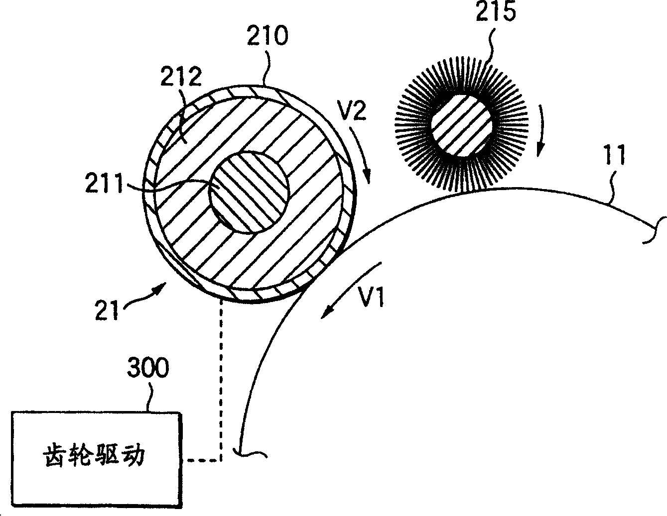
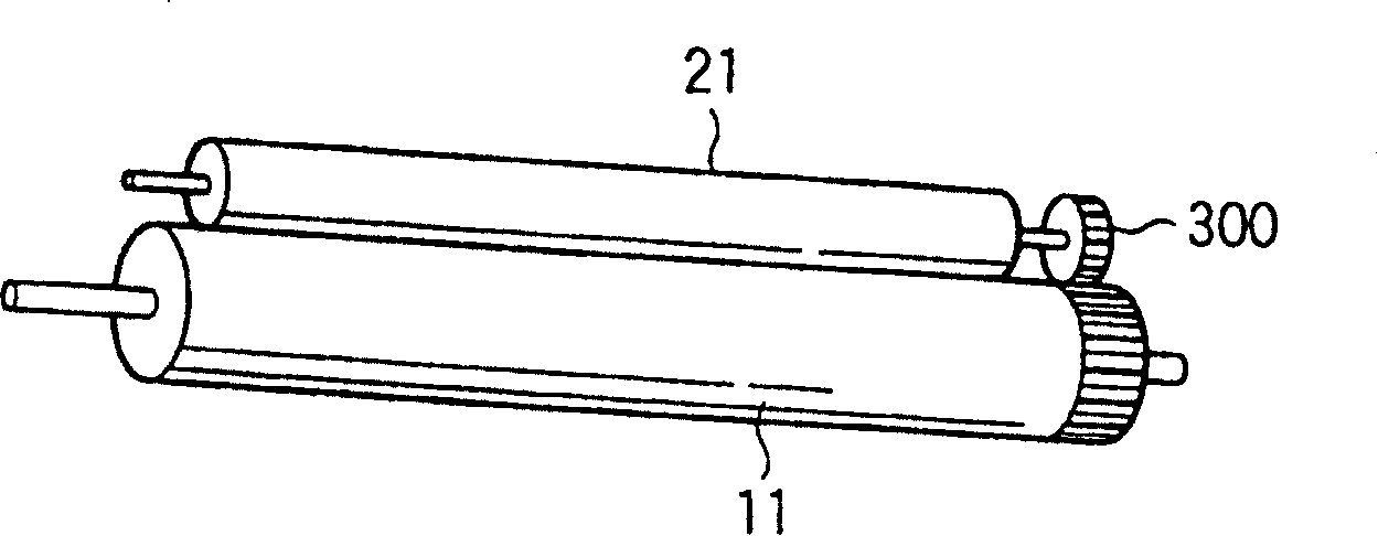
A charger has a cylindrical rotation tube coming in contact with an image receptor on which a toner image is formed, the rotation tube to which a predetermined charge bias is applied, and drive means for driving the rotation tube at a predetermined peripheral speed, the charger for uniformly charging the surface of the image receptor. When the peripheral speed of the image receptor is V1 and the peripheral speed of the rotation tube is V2, the following relation is satisfied: 1.01<(V2 / V1)<=1.10.

Description

technical field [0001] The present invention relates to a method for charging the surface of an image carrier such as a photoconductive drum on which a toner image is formed with a uniform potential in an image forming apparatus such as an electrophotographic copier or a laser beam printer. A charger, in particular, relates to an improvement for keeping the surface of an image carrier and the surface of a charger in a clean state for a long period of time. Background technique [0002] In an electrophotographic copier or a laser beam printer, the surface of an image bearing member such as a photoconductive drum is uniformly charged, and then exposed according to image information to form an electrostatic latent image, and the electrostatic latent image is formed in the toner Development is performed to form a toner image of a visible image, and finally, the toner image is transferred to an image carrier such as an intermediate transfer body or recording paper to form a recor...

Claims


Application Information

Patent Timeline
Patent Type & Authority Patents(China)
IPC IPC(8): G03G15/02
CPCG03G15/0216G03G15/02
Inventor 大野茂雄山本隆一北河裕介山井和也归山忠士井出典孝高桥伦明三桥利彦広崎悟佐藤昌宏小泉弘光
Owner FUJIFILM BUSINESS INNOVATION CORP
Learn More