Method for supporting a propelled flying object during take-off and/or landing

A power device and aircraft technology, applied in ground devices, aircraft parts, transportation and packaging, etc., can solve the problems of high training costs for air crew, achieve the effects of preventing aircraft from overheating, flexible use, and improving safety

Inactive Publication Date: 2008-05-14
克劳斯·沃尔特
View PDF4 Cites 0 Cited by
  • Summary
  • Abstract
  • Description
  • Claims
  • Application Information

AI Technical Summary

Problems solved by technology

This approach implies high

Method used


Image

  • Method for supporting a propelled flying object during take-off and/or landing
  • Method for supporting a propelled flying object during take-off and/or landing

Examples


Embodiment Construction

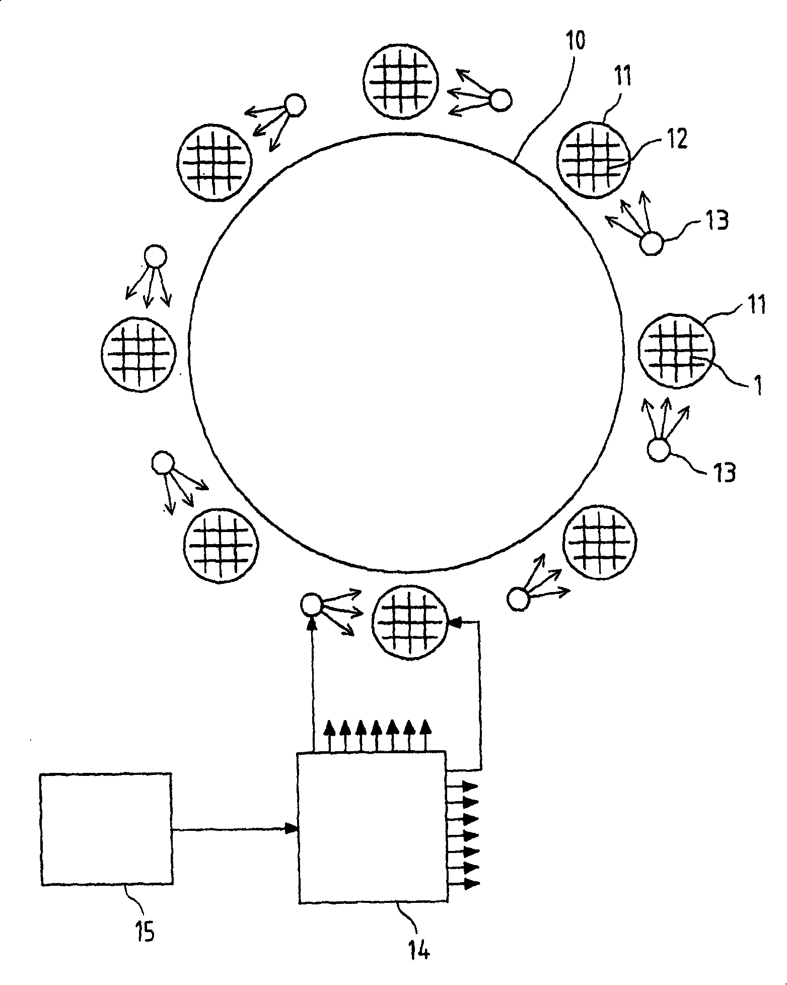
[0041] figure 1 A take-off and landing device for supporting take-off and landing of an aircraft is schematically shown. Here the aircraft may be a conventional type of aircraft.

[0042] The take-off and landing device has a circular take-off and landing area 10 . Eight large turbofans 11 are installed at regular intervals around the takeoff and landing area 10 . Each turbofan 11 is rotatably installed and has a temperature adjusting element. The temperature adjustment element comprises a grid-like insert 12 in the air outlet area of ​​the respective turbofan 11, wherein the temperature of the grid-like insert 12 is adjustable. In addition, each turbofan 11 is assigned a spraying device 13 which sprays water droplets in the air outlet region of the turbofan 11 .

[0043] In addition, the take-off and landing device has a computer-based controller 14 . The regulator 14 is connected to a detection and reception device 15 . The latter includes temperature sensors and a rec...


PUM


Abstract

The invention relates to a method for supporting a propelled flying object during take-off and/or landing. Support is given by means of a fluidic current, which is generated at a fixed point in relation to a take-off or landing surface (10) and which transfers energy to the flying object. The invention also relates to a device comprising a fluidic current generator (11) for producing said fluidic current.

Description

technical field [0001] The invention relates to a method and device for supporting the landing and / or take-off of an aircraft with a power plant. Background technique [0002] An aircraft here refers to any object suitable for moving without contact with the ground in the atmosphere of a planet by its own power plant, such as an aircraft. [0003] The take-off and landing procedures represent a special challenge for such aircraft, both structurally and operationally. [0004] Long take-off and landing runways are often required for take-off and landing of aircraft. But preparing long takeoff and landing runways is time-consuming and expensive. Plus there isn't enough space available for regular takeoff and landing runways everywhere. This situation occurs especially on shipboard landing facilities, but it can also cause problems in other places, such as in mountainous areas. In this case, it may be necessary to support the landing process with the aid of catching lines o...

Claims


Application Information

Patent Timeline
IPC IPC(8): B64F1/36
Inventor 克劳斯.沃尔特
Owner 克劳斯·沃尔特
Why Eureka
Try Eureka