
Optical signal collecting and on-line monitoring method for electric power equipment internal failure

A technology for electrical equipment and internal faults, applied in the direction of measuring electricity, measuring devices, measuring electrical variables, etc., can solve problems such as errors, misjudgment of discharge faults, inability to distinguish between optical signals, etc., to achieve low cost, reduce equipment damage, Ease of promotion

Inactive Publication Date: 2008-04-30
孙艺夫
View PDF3 Cites 0 Cited by
  • Summary
  • Abstract
  • Description
  • Claims
  • Application Information

AI Technical Summary

Problems solved by technology

The literature has recorded a device that collects optical signals to monitor discharge faults, but the device cannot distinguish the detected optical signals into optical signals generated by overheating faults and optical signals generated by discharge faults, so the type of fault cannot be judged when the optical signal is generated. Simply diagnosing the discharge fault will be wrong, and judging the strength of the discharge fault based on the measured signal value will also cause misjudgment, because the optical signal generated by the overheating fault is likely to interfere with the measurement results

Method used

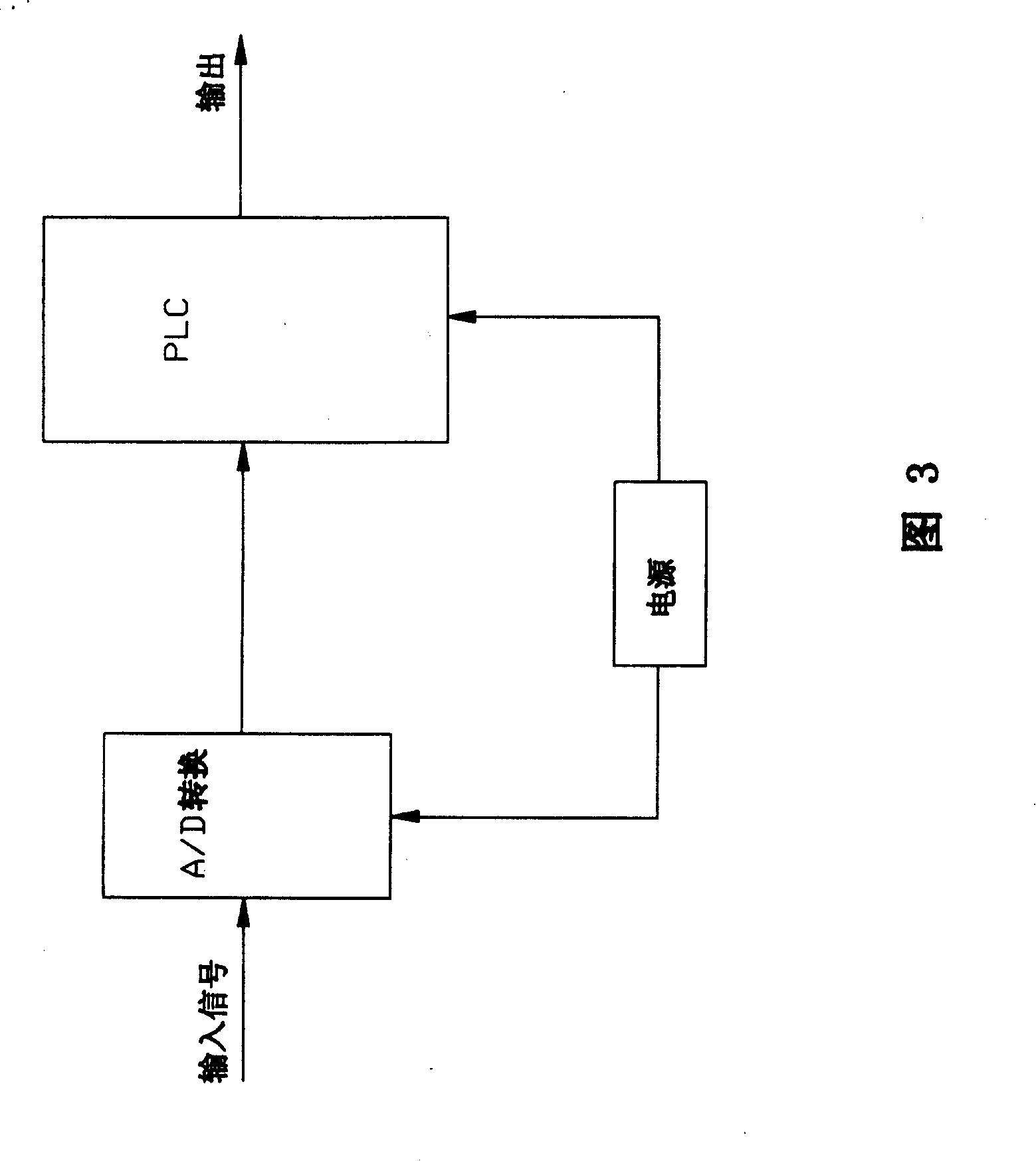

Image

  • Optical signal collecting and on-line monitoring method for electric power equipment internal failure
  • Optical signal collecting and on-line monitoring method for electric power equipment internal failure
  • Optical signal collecting and on-line monitoring method for electric power equipment internal failure

Examples


Embodiment Construction

[0019] Step 1. Use optical fibers to collect optical signals generated due to failures inside the airtight equipment: pre-arrange optical fibers (groups) 2 inside the airtight power equipment 1, especially the ones with good light transmission and insulation performance in the near-infrared to near-ultraviolet wavelength region The outer sheath of the quartz fiber is made of polytetrafluoroethylene material or epoxy resin material with a temperature resistance of more than 100°C, long-term stability in the insulating medium (such as transformer oil) and good insulation performance, so that the input of the fiber The end faces the monitored part, and the fiber group composed of multiple optical fibers can be arranged according to the needs to monitor various fault-prone parts inside the equipment. In order to improve the optical signal receiving effect of the optical fiber, a lens can be added in front of the input end, such as connecting a hemispherical lens to the optical fibe...


PUM


Abstract

The light signal the fault part inside closed electric power equipment produces is acquired with optical fiber, signal distinguished and amplified in the signal distinguishing and amplifying circuit to separate discharge signal and / or overheat signal; and the type, degree and position of the fault inside the equipment are judged in the signal processing circuit based on the signal type, size and distribution. The said method is simple, practical, accurate and reliable, and may be used in the in-situ monitoring of main transformer equipment.

Description

Technical field: [0001] The invention belongs to the technical field of power equipment detection, and further relates to the online monitoring of internal faults of power equipment such as airtight transformers and switches under operating conditions. Background technique: [0002] It is an important condition to ensure the safety of the power grid to grasp the operation status of the power equipment and find out the internal faults of the equipment in time. At present, most of the existing on-line monitoring methods are based on the collection of electrical signals, acoustic signals and medium decomposition signals to realize online monitoring. Because power equipment works in high voltage, strong electromagnetic field and large vibration and noise environment, it is often difficult to accurately separate the electrical and acoustic signals of discharge pulses generated by faults from complex interference, resulting in complex detection equipment and poor reliability; The...

Claims


Application Information

Patent Timeline
Patent Type & Authority Patents(China)
IPC IPC(8): G01J3/28G01R31/00H02H3/22
Inventor 孙艺夫
Owner 孙艺夫
Learn More