
Permanent-magnet rotary motor

A technology of permanent magnets and motors, which is applied in the direction of magnetic circuit rotating parts, motors, synchronous motors with static armatures and rotating magnets, etc., can solve problems such as increased power consumption, increased motor size, and increased weight.

Inactive Publication Date: 2008-04-09
HONDA MOTOR CO LTD
View PDF6 Cites 3 Cited by
  • Summary
  • Abstract
  • Description
  • Claims
  • Application Information

AI Technical Summary

Problems solved by technology

Therefore, in order to obtain more driving torque, it is necessary to increase the size of the permanent magnet, or increase the excitation current of the stator coil, but this will inevitably lead to an increase in the size of the motor, increase in weight, or increase in power consumption
[0005] In addition, when using one motor as a starter motor when starting the engine and as a generator when the vehicle is running, if the permanent magnet is enlarged as described above, it can be used as a starter motor. To obtain a large driving torque, on the contrary, when it is used as a generator, since it is necessary to generate a large amount of electricity that exceeds the required amount, the torque (passive torque) required by the engine E to drive the starter and generator increased

Method used


Image

  • Permanent-magnet rotary motor
  • Permanent-magnet rotary motor
  • Permanent-magnet rotary motor

Examples


Embodiment Construction

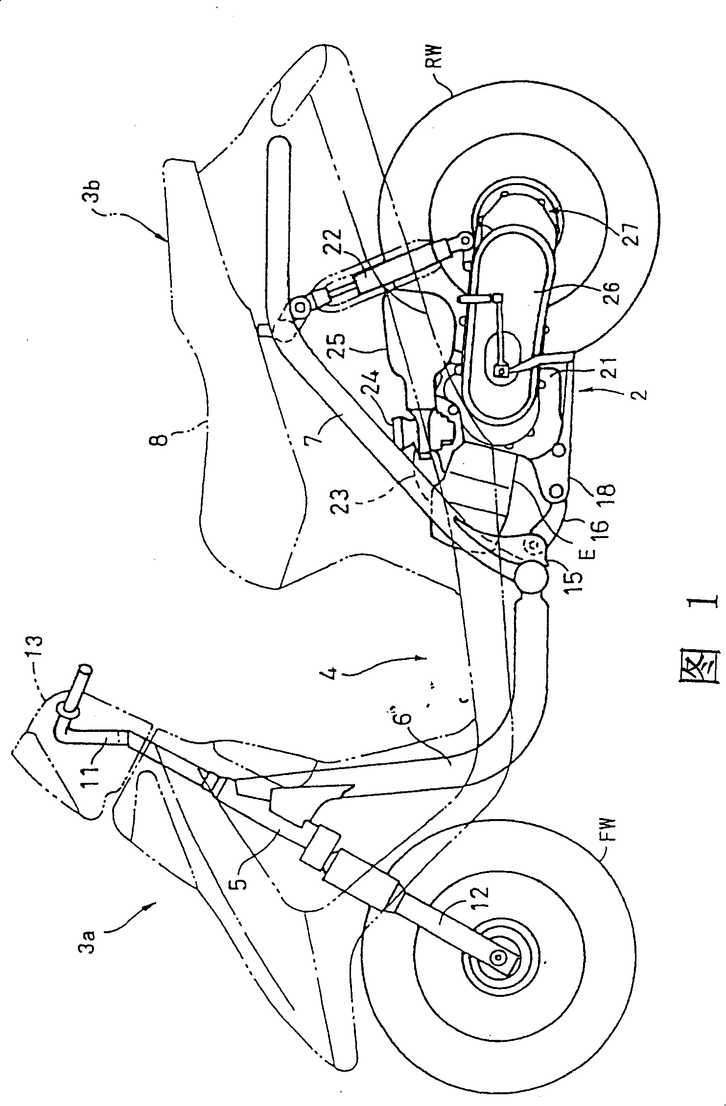
[0031] Hereinafter, the present invention will be described in detail with reference to the accompanying drawings. Fig. 1 is an overall side view of a scooter to which a permanent magnet type rotary motor according to the present invention is applied to a starter-generator.

[0032] The vehicle body front portion 3 a and the vehicle body rear portion 3 b are connected to each other by a low floor portion 4 , and a frame constituting a frame of the vehicle body is roughly composed of a down pipe 6 and a main pipe 7 . A fuel tank and a storage box (both not shown) are supported by a main pipe 7, and a vehicle seat 8 is arranged above it.

[0033] In the vehicle body front portion 3a, a handlebar 11 is supported on and above a steering head 5, a front fork 12 extends downward, and a front wheel FW is supported at the lower end. The upper part of the handlebar 11 is covered by a handlebar cover 13 which also serves as a dashboard. A bracket 15 protrudes from the lower end of the...


PUM


Abstract

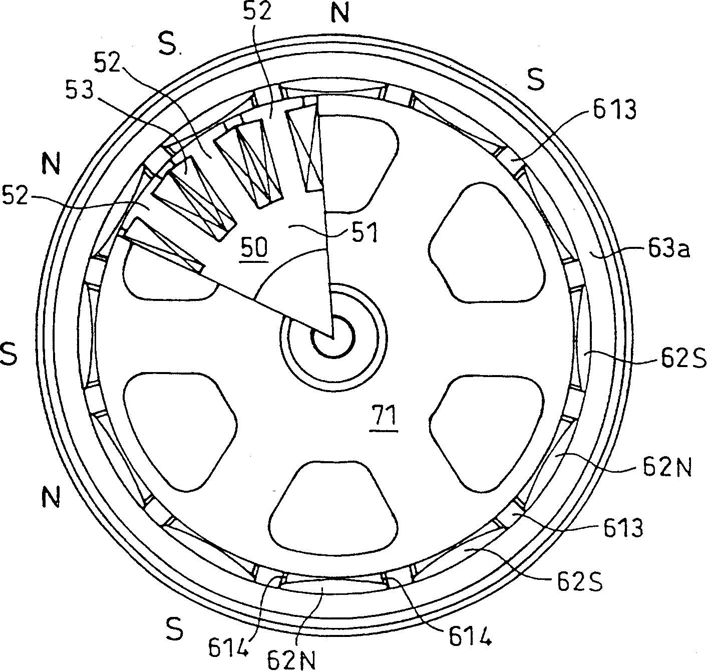
The invention provides a permanent magnet rotary electric motor as a starter-generator apparatus with which high driving torque is obtained when it functions as a starter motor whereas the driven torque can be suppressed low when it functions as a generator. The permanent magnet rotary electric motor includes a stator 50 and a winding 53 on the stator, and a substantially cylindrical rotor yoke 61 including a plurality of permanent magnets 62 disposed along a circumferential direction and rotatable around the stator 50 and wherein the rotor yoke 61 has a commutating pole portion 613 between each adjacent ones of the permanent magnets 62, is constructed such that a gap 612, 614 is provided at a portion between each of the permanent magnets 62 and the rotor yoke 61.

Description

technical field [0001] The present invention relates to a permanent magnet type rotary motor in which a rotor yoke arranged with a plurality of permanent magnets in the circumferential direction rotates on the outer periphery of a stator, and the rotor yoke has auxiliary poles between the permanent magnets, and is particularly suitable as a starter motor for an engine. A permanent magnet rotary motor that is both a machine and a generator. Background technique [0002] Conventionally, a starter motor and a generator for an engine are separately equipped, but for example, Japanese Patent Laid-Open No. 10-148142 discloses a starter-generator unit in which various functions are combined. [0003] On the other hand, as a starter motor for an engine, there is known an outer type permanent magnet type rotary motor in which a cylindrical rotor yoke rotates on the outer periphery of a stator. In addition, for example, Japanese Patent Laid-Open No. 8-275476 discloses a permanent mag...

Claims


Application Information

Patent Timeline
Patent Type & Authority Patents(China)
IPC IPC(8): H02K21/22H02K1/27H02K21/26H02K1/17
CPCH02K21/222H02K1/2786B60L15/007B60L15/20B60L15/2054H02K1/148H02K1/272H02K7/006B60L2210/10B60L2210/40B60L50/16Y02T10/64Y02T10/72Y02T10/7072H02K1/2791H02K21/26H02K1/17
Inventor 柴田和己田中邦彦小丿泽圣二
Owner HONDA MOTOR CO LTD
Learn More