Programmable optical component for spatially controlling the intensity of beam of radiation

A technology for controlling radiation and optical components, which is applied in the field of photolithography and optical scanning devices, can solve the problems of high cost, trouble, and time-consuming photomask, and achieve the effect of small field intensity

Inactive Publication Date: 2008-03-26
KONINKLIJKE PHILIPS ELECTRONICS NV
View PDF5 Cites 2 Cited by
  • Summary
  • Abstract
  • Description
  • Claims
  • Application Information

AI Technical Summary

Problems solved by technology

[0007] Fabrication of photomasks is a time consuming and cumbersome process which makes such masks expensive
Photolithographic fabrication using photomasks is a costly method if multiple redesigns of the photomask are necessary or in cases where customer-specific devices must be fabricated, ie relatively small quantities of identical devices

Method used


Image

  • Programmable optical component for spatially controlling the intensity of beam of radiation
  • Programmable optical component for spatially controlling the intensity of beam of radiation
  • Programmable optical component for spatially controlling the intensity of beam of radiation

Examples


Embodiment Construction

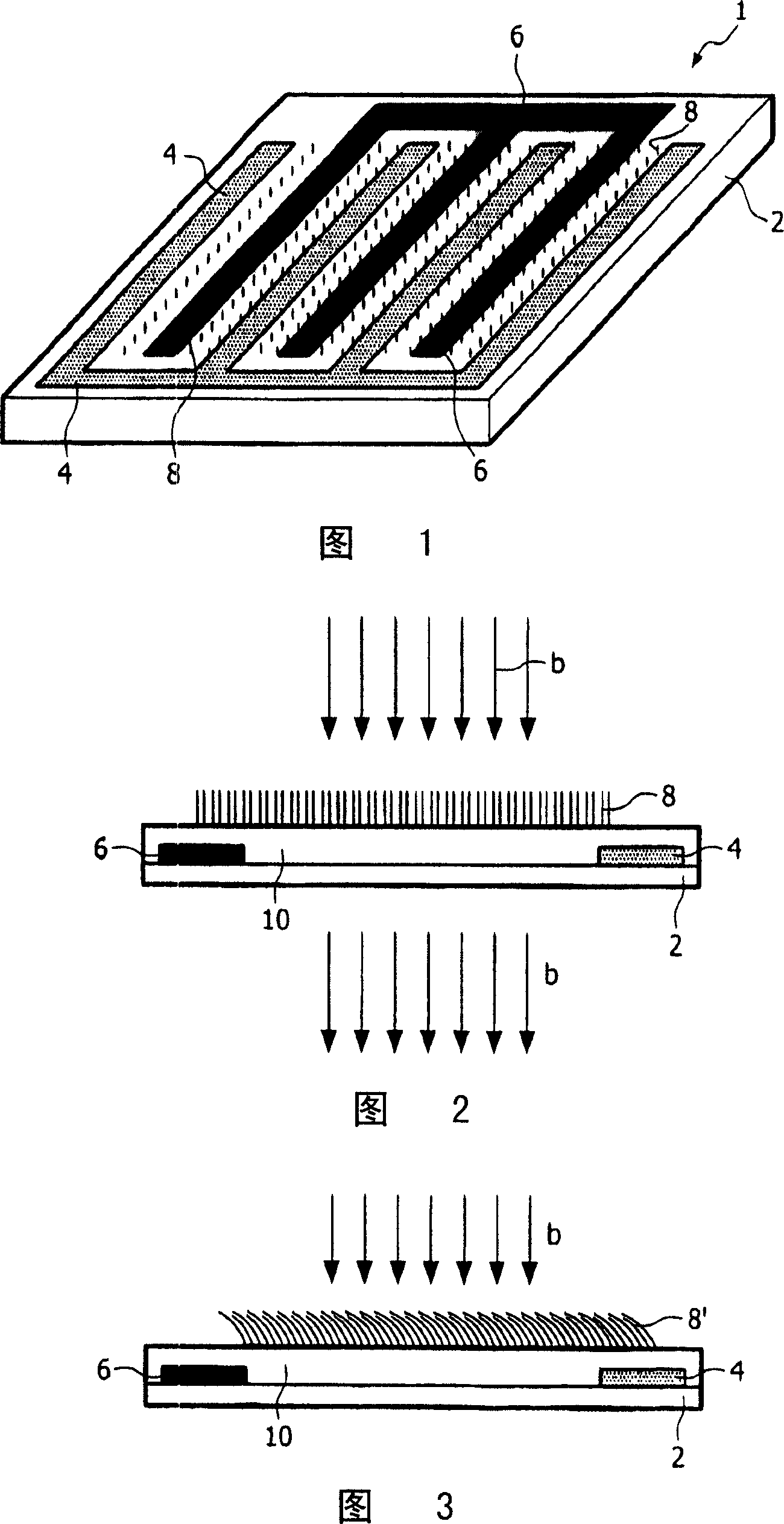
[0076] The part shown in Fig. 1 comprises a substrate 2, for example a transparent substrate such as a glass or transparent plastic substrate. The upper side of the substrate is provided with first and second electrodes 4 and 6, respectively, and with bendable nano-elements 8 arranged between the electrodes. The electrodes 4 and 6 may be interdigitated, ie parts of a first electrode are arranged between parts of a second electrode. This electrode structure is very suitable for the manufacture of diffraction gratings, whereby the stripes with bendable nano-elements form the grating stripes and the electrode part forms the middle stripes. The electrodes 4 and 6 shown in FIG. 1 have four fingers and three fingers, respectively. However, the number of fingers can be chosen freely, and in practice the number of fingers can be higher for a diffraction grating. The electrodes are transparent and can be fabricated, for example, from indium tin oxide (ITO).

[0077] As shown in the ...


PUM

PropertyMeasurementUnit
diameteraaaaaaaaaa
thicknessaaaaaaaaaa
thicknessaaaaaaaaaa

Abstract

A programmable optical component (10) for spatially controlling the intensity of a beam of radiation (b), which component comprises a programmable layer which is divided in programmable elements (4,6,8), characterized in that each programmable element comprises bendable nano-elements (8) which are switchable between a non-bend state (8) and a bend state (8') by means of a driver field. In their bend state the nano-elements absorb radiation. The programmable element may be a switchable diffraction grating or a programmable mask.

Description

technical field [0001] The invention relates to a programmable optical component for spatially controlling the intensity of a radiation beam, the component comprising a programmable layer distributed in a programmable element. The invention also relates to an optical scanning device comprising the component and a photolithographic method in which the component is used. Background technique [0002] Spatial control is understood to mean controlling the intensity of discrete portions of the radiation beam incident on the element as well as controlling the direction of propagation of the radiation from the beam. [0003] An example of a programmable optical component is a switchable diffractive component, ie a diffractive element that can be set to an on state and an off state, whereby in the off state the diffractive or programmable layer forms a flat parallel layer. Another example of a programmable optical component is a programmable mask, such as a photolithographic mask. ...

Claims


Application Information

Patent Timeline
Patent Type & Authority Patents(China)
IPC IPC(8): G02B26/02G02B26/08G02F1/31G03F7/20
CPCG03F7/70291G02B26/0808G02B26/08B82Y15/00
Inventor R·库尔特G·W·特胡夫特R·F·M·亨德里克斯
Owner KONINKLIJKE PHILIPS ELECTRONICS NV
Why Eureka
Try Eureka