


Quick Research
Generate reliable direction feasibility study reports for your R&D in just a few steps.

Technical Q&A
Discover and master advanced knowledge NOW. Basics, ideas, possibilities, all at once.

Find Solutions
As an expert in R&D theories, this can generate solutions to your technical problems instantly.

Evaluate Feasibility
Analyze your overall solution with one click, know your potential R&D risks in advance.

Monitor Landscape
Get weekly tech updates, stay abreast of the latest tech innovations and key insights.
Refrigerant compressor
A refrigerant and compressor technology, applied in additives, mechanical equipment, machines/engines, etc., can solve the problems of exhaust reed seal failure and poor compression, and achieve high reliability and high efficiency.
- Summary
- Abstract
- Description
- Claims
- Application Information
AI Technical Summary
Problems solved by technology
Method used
Image

Examples
Embodiment 1
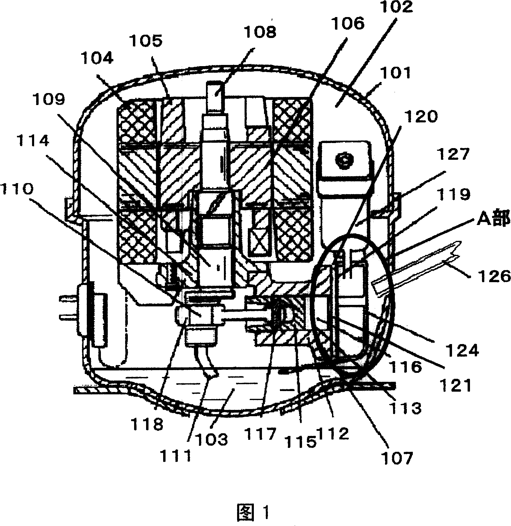
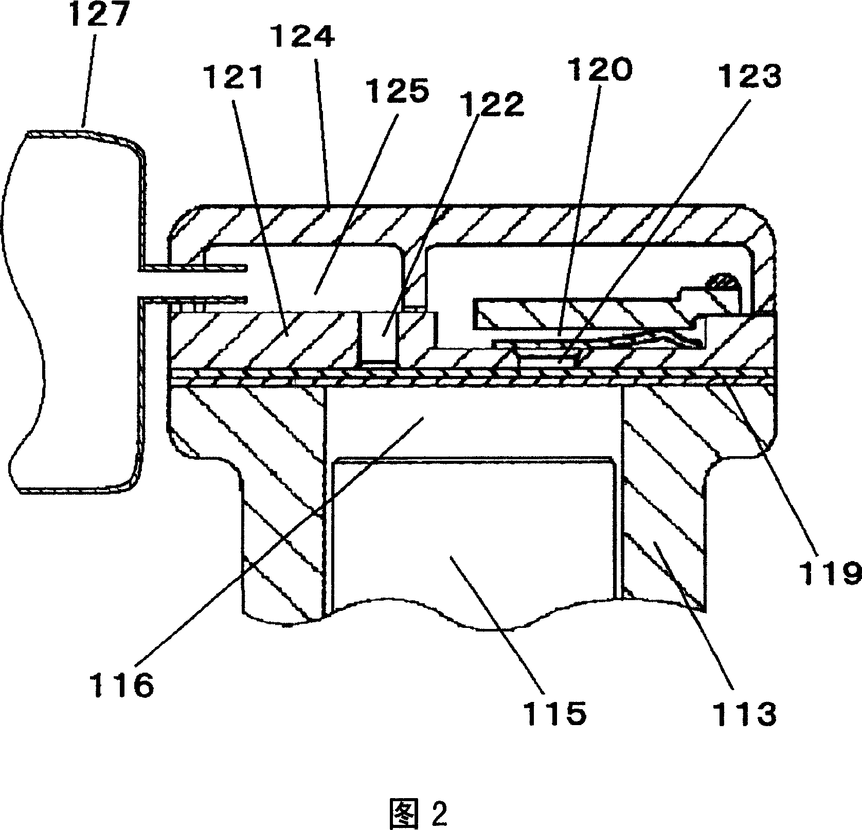
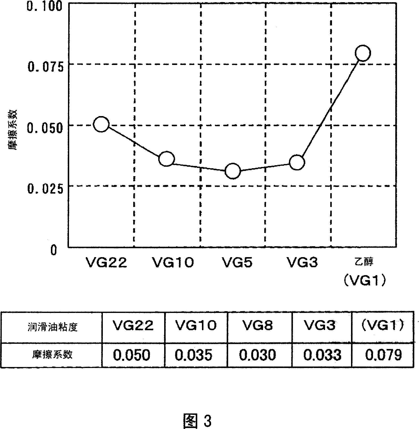
[0049] Fig. 1 is a cross-sectional view of a refrigerant compressor in Embodiment 1 of the present invention, Fig. 2 is an enlarged schematic diagram of part A in Fig. 1 , and Fig. 3 is a schematic diagram of friction coefficient characteristics under different lubricating oil viscosities, Fig. 4 is a schematic diagram of compressor efficiency characteristics under different lubricating oil viscosities.
[0050] In Fig. 1, the interior of the sealed casing 101 is filled with a refrigerant gas 102 composed of R600a, and at the same time, lubricating oil composed of mineral oil 103 with a VG of 5 is stored at the bottom, and the boiling point is 350°C or higher. The volume ratio is 10% to 30%, and the volume ratio of components with a boiling point of 300°C or lower is 50% to 70%. In addition, a motor mechanism 106 composed of a stator 104 and a rotor 105 and a reciprocating compression mechanism 107 driven by the motor mechanism 106 are installed in the sealed housing 101 .
...
Embodiment 2
[0081] Fig. 5 is a schematic diagram of the refrigerant compressor in this embodiment, Fig. 6 is an enlarged schematic diagram of part A in Fig. 5, Fig. 7 is a sectional view of B-B in Fig. 5, and Fig. 8 is a schematic diagram of some important structures in Fig. 7 The schematic diagram is enlarged, and Fig. 9 is a graph showing the extraction characteristics of oligomers under different lubricating oil viscosities.
[0082] As shown in FIGS. 5-8 , lubricating oil 202 is stored in the sealed case 201 , and these lubricating oils 202 are composed of a single mineral oil with substantially the same evaporation temperature, and its viscosity is V65. Meanwhile, a compression mechanism 203 used as a compression component and a distributed winding induction motor 204 used as an electric mechanism to drive the compression mechanism 203 are also provided in the sealed casing 201 . In addition, the refrigerant used is R600a.
[0083] The motor 204 is wound with a main winding 205 thro...
Embodiment 3
[0099] Fig. 10 is a schematic diagram of the refrigerant compressor in this embodiment, Fig. 11 is an enlarged schematic diagram of part C in Fig. 10, Fig. 12 is a D-D sectional view of Fig. 10, and Fig. 13 is a diagram of some important structures in Fig. 12 Zoom in on the schematic.
[0100] As shown in Fig. 10 and Fig. 11, a lubricating oil 302 with a viscosity of VG8, which is composed of a single mineral oil with substantially the same evaporation temperature, is stored in the sealed housing 301, and a compression mechanism 303 is also provided to drive the compression mechanism. 303 of the electric motor 304 . The motor 304 is a concentrated winding frequency converter motor. The refrigerant used is R600a.
[0101] In the motor 304, the main winding 305 through which current supplied from a commercial power source (not shown) through a power supply circuit (not shown) flows is wound so as to pass between adjacent coil slots 307 (Fig. 12). The insulator 333 is inserte...
PUM
 Abstract
Description
Claims
Application Information
 - R&D Engineer
- R&D Manager
- IP Professional
- Industry Leading Data Capabilities
- Powerful AI technology
- Patent DNA Extraction
Browse by: Latest US Patents, China's latest patents, Technical Efficacy Thesaurus, Application Domain, Technology Topic, Popular Technical Reports.
© 2024 PatSnap. All rights reserved.Legal|Privacy policy|Modern Slavery Act Transparency Statement|Sitemap|About US| Contact US: help@patsnap.com