Control method of induction motor

A technology for induction motors and control methods, which is applied in the direction of AC motor control, starters of single multi-phase induction motors, motor generators/starters, etc., and can solve the problem of complex circuit structures, frequency and circuit speed dependent on commercial power supply 1 Complex structure and other issues

Inactive Publication Date: 2008-03-05
FUJI ELECTRIC CO LTD +1
View PDF5 Cites 0 Cited by
  • Summary
  • Abstract
  • Description
  • Claims
  • Application Information

AI Technical Summary

Problems solved by technology

As a result, the VVVF inverter 2 has a complicated circuit structure compared to a general-purpose VVVF inverter that outputs only an AC voltage of a required frequency and voltage.
In addition, switching circuit 3, AC choke 6, timing control circuit 7, etc. are required, and the overall structure of the circuit shown in Fig. 9 is also complicated.
[0014] In addition, the inrush current from the VVVF inverter 2 to the induction motor 4 is suppressed by the AC choke 6 , but at this time, the rotation speed of the induction motor 4 fluctuates, and this fluctuation may be undesirable for the load 5
[0015] Moreover, since the induction motor 4, which requires a very large driving torque when starting the above-mentioned textile machinery, etc., is started by the power supply from the commercial power supply 1, although the operation load of the VVVF inverter 2 can be reduced, there is a problem after the induction motor 4 is started. The difficulty that the rotational speed depends on the frequency of the commercial power supply 1, as a result, when the output frequency required by the induction motor 4 is different from the frequency of the commercial power supply 1, it is necessary to start supplying power from the VVVF inverter 2, and eventually the induction motor 4 becomes It takes time for the load 5 to be in the working state for the operation of the AC voltage of the required frequency

Method used


Image

  • Control method of induction motor
  • Control method of induction motor
  • Control method of induction motor

Examples


Embodiment Construction

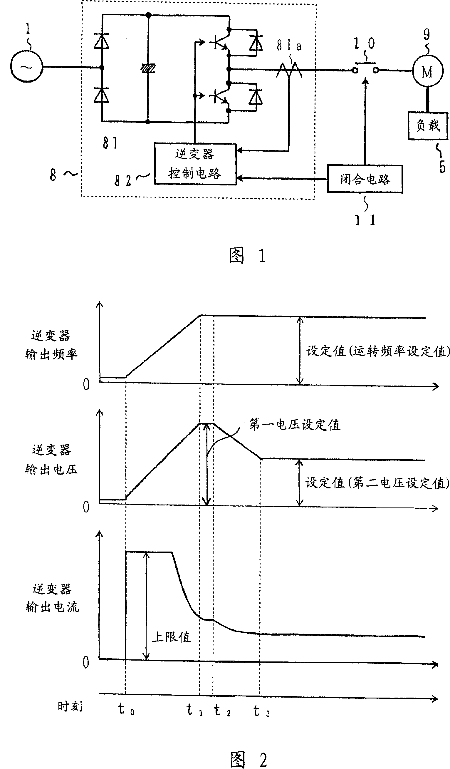
[0042] 1 is a circuit configuration diagram showing a first embodiment of a method for controlling an induction motor according to the present invention, and components having the same functions as those in the conventional configuration shown in FIG. 9 are assigned the same reference numerals.

[0043] That is, in the circuit structure shown in FIG. 1, in addition to the commercial power supply 1 and the load 5, it also includes: a VVVF inverter 8, an induction motor 9 connected in a delta connection with primary coils, an electromagnetic relay 10, and a closed circuit of the electromagnetic relay 10 11. The VVVF inverter 8 includes an inverter main circuit 81 and an inverter control circuit 82 . The inverter main circuit 81 converts the AC voltage of the commercial power supply 1 into a DC voltage with a diode rectifier and a smoothing capacitor, and connects an antiparallel circuit of transistors and diodes that convert the DC voltage into an AC voltage in a bridge. The in...


PUM


Abstract

A control method of an induction motor suitable for an induction motor requiring a very large driving torque at the time of starting or acceleration of a textile machine, or the like, wherein a variable voltage variable frequency (VVVF) inverter (8) supplying power to the primary winding of the induction motor (9) increases its output voltage and output frequency after start while keeping the output current from the inverter lower than a specified current limit level, lowers only the output voltage of the VVVF inverter (8) down to a specified voltage set level after finishing acceleration of the induction motor (9), and then supplies an AC voltage corresponding to the frequency set level and the voltage set level continuously from the VVVF inverter (8) to the induction motor (9).

Description

technical field [0001] In particular, the present invention relates to a control method of an induction motor used as a power source of an industrial machine such as a textile machine that requires a very large driving torque for starting. Background technique [0002] Conventionally, as such an induction motor control method, first, the induction motor is connected to a commercial power source to start, and after the motor reaches approximately a normal rotation speed, the induction motor is disconnected from the commercial power source, and instead, it is connected to an optional The output of the variable-voltage variable-frequency inverter that sets the frequency (for example, refer to Patent Document 1). [0003] However, problems with the induction motor control method of Patent Document 1 described above will be described below based on a circuit configuration diagram of a conventional induction motor control method shown in FIG. 9 . [0004] That is, in FIG. 9, 1 is...

Claims


Application Information

Patent Timeline
Patent Type & Authority Patents(China)
IPC IPC(8): H02P1/30H02P27/06H02P1/26H02P1/28
CPCH02P1/30H02P1/28H02P27/06
Inventor 高木靖久石田一郎高野敏雄高岛淳
Owner FUJI ELECTRIC CO LTD
Why Eureka
Try Eureka