Component structure of deposition chamber

A technology of component structure and deposition chamber, applied in the field of deposition chamber, can solve the problems of lower qualification rate, inclination, difficult positioning of subsequent processes, etc., to achieve the effect of improving the qualification rate and reducing the probability of wafer rework

Inactive Publication Date: 2008-03-05
MACRONIX INT CO LTD
View PDF6 Cites 0 Cited by
  • Summary
  • Abstract
  • Description
  • Claims
  • Application Information

AI Technical Summary

Problems solved by technology

[0005] However, the above-mentioned screw used to discharge the accumulated charge is often too small because of its allowable change of angle. The so-called "allowable change of angle" refers to the ability of the screw placed in the small hole to move obliquely. Angle range, and a small allowable angle change will cause part of the screw to be unable to contact the pressure ring, so that the pressure ring that originally presses down the wafer in parallel will be tilted by the contact of the screw at some positions
[0006] Since the pressure ring is tilted, the part of the wafer originally covered by the protrusion of the pressure ring will be exposed, and a clear positioning mark cannot be obtained after the deposition process, resulting in difficulties in positioning in the subsequent process
If you want to ensure the correct positioning of the subsequent process, you need to spend extra cost and time to rework the wafer (rework), but this will lead to disadvantages such as lower yield

Method used


Image

  • Component structure of deposition chamber
  • Component structure of deposition chamber

Examples


Embodiment Construction

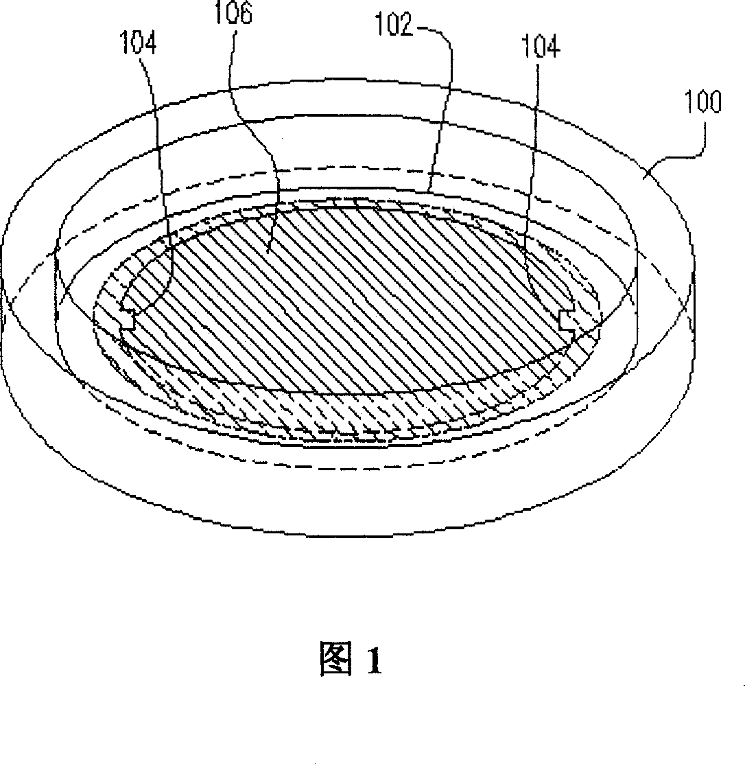
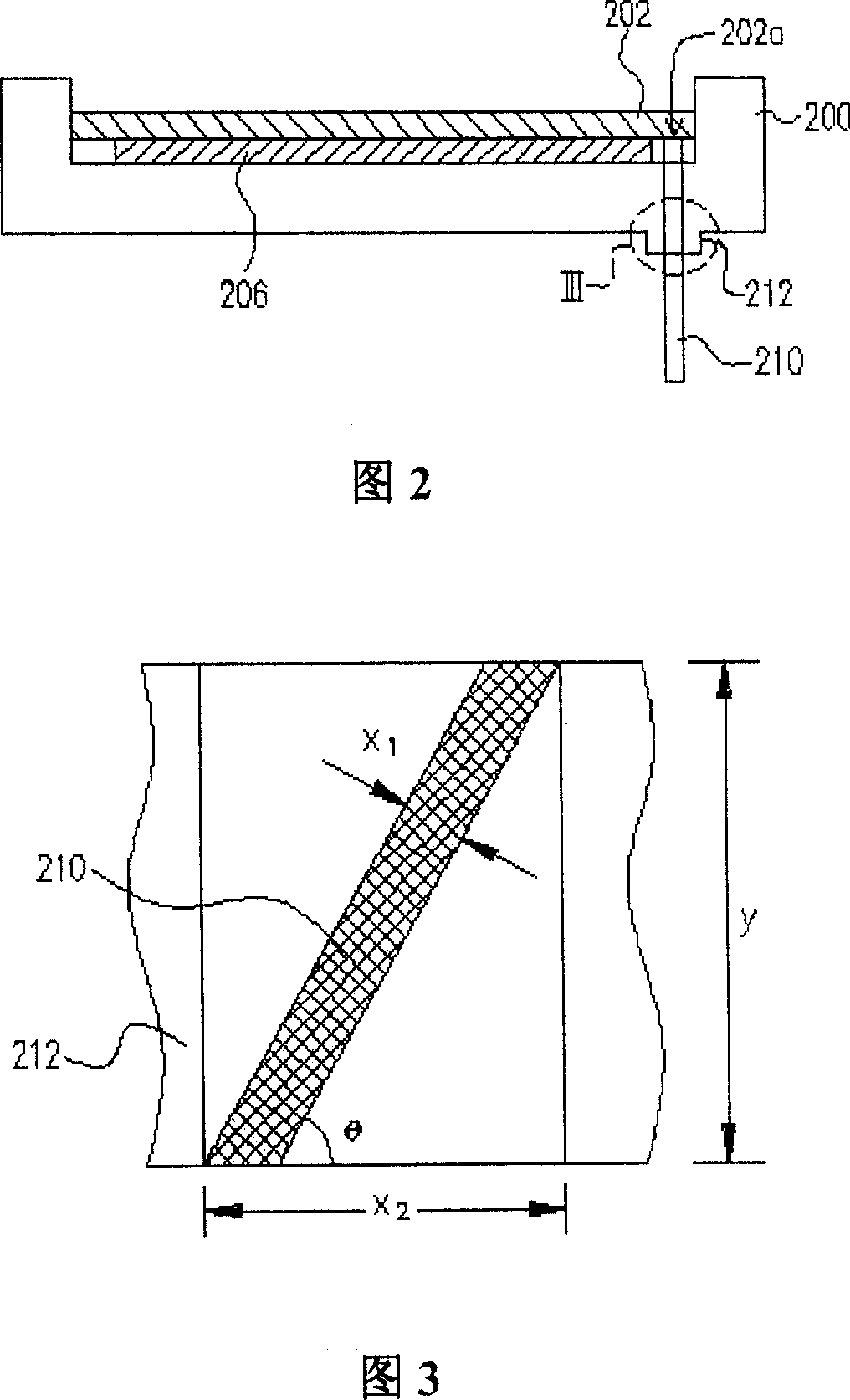
[0027] The present invention can be applied to any deposition chamber used in the deposition process. As shown in FIG. 2 , the device is used to deposit a thin film on a wafer while forming a mark for positioning.

[0028] FIG. 2 is a schematic side view of the component structure of a deposition chamber according to a preferred embodiment of the present invention. Please refer to FIG. 2, the parts of the deposition chamber include a shell (shield) 200, a pressure ring (clamp) 202, a screw (screw) 210 and an insulating part (isolator) 212, wherein the shell 200 is, for example, a wafer seat, The material of the screw 210 is a conductive material such as brass; and the material of the insulating part 212 is ceramic material, and its shape can be circular. Although only one screw 210 is shown in this figure, actually the number of screws 210 can be increased as needed, so the number of screws 210 is not limited to one. In addition, the insulating part 212 is integrally formed w...


PUM


Abstract

The invention relates to a component structure of deposition room, with a case, a press ring in the case and a screw contacting the press ring through the case to release the charges accumulated by the press ring. Besides, the case also includes an insulating part that surrounds the screw to isolate the screw from the case, wherein the allowable angle variation of the screw is greater than 23.2.

Description

technical field [0001] The present invention relates to a deposition chamber, and more particularly to a part structure of a deposition chamber. Background technique [0002] In the semiconductor process, in order to facilitate subsequent processes such as the alignment process such as the exposure process, currently most of the deposition process uses a pressure ring with a protrusion for positioning in the wafer holder in the deposition chamber to fix the wafer. Afterwards, the deposition process is carried out so as to simultaneously deposit the predetermined thin film on the wafer and form a positioning mark (mark), and the structure of the wafer seat in the deposition chamber and the pressure ring with the positioning protrusion is shown in FIG. 1 . [0003] FIG. 1 is a schematic perspective view of a known component structure of a deposition chamber. Referring to FIG. 1 , a clamp 102 is disposed in a wafer seat 100 in a deposition chamber, and the clamp 102 has two pr...

Claims


Application Information

Patent Timeline
Patent Type & Authority Patents(China)
IPC IPC(8): H01L21/20H01L21/66C23C16/00C23C14/00
Inventor 彭俊宁
Owner MACRONIX INT CO LTD
Why Eureka
Try Eureka