
Flanging arrangement for wall hole of thin metal pipe

A thin metal and outer flanging technology, applied in the field of processing equipment, can solve the problems of difficult to improve production efficiency, complicated flanging process, increase water circulation resistance, etc., and achieve the effect of improving work efficiency and simple flanging process

Inactive Publication Date: 2008-02-20
夏纪运
View PDF8 Cites 2 Cited by
  • Summary
  • Abstract
  • Description
  • Claims
  • Application Information

AI Technical Summary

Problems solved by technology

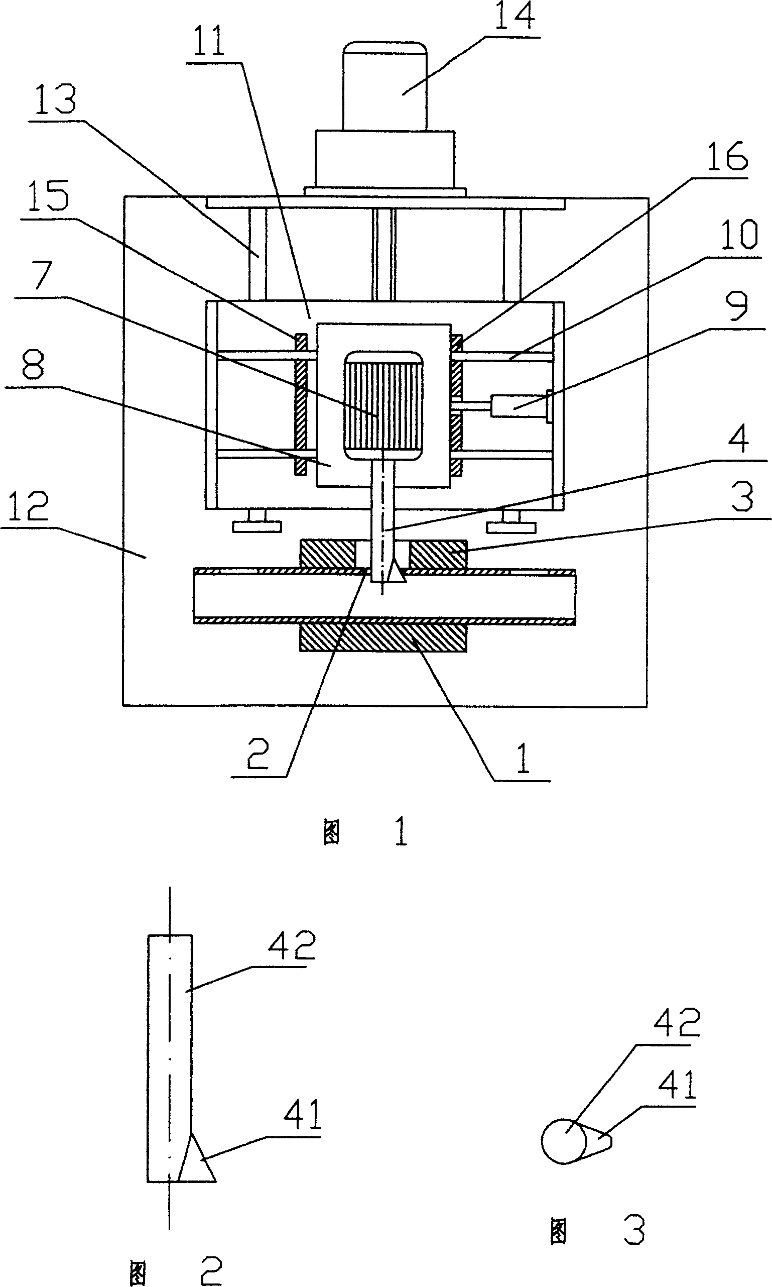
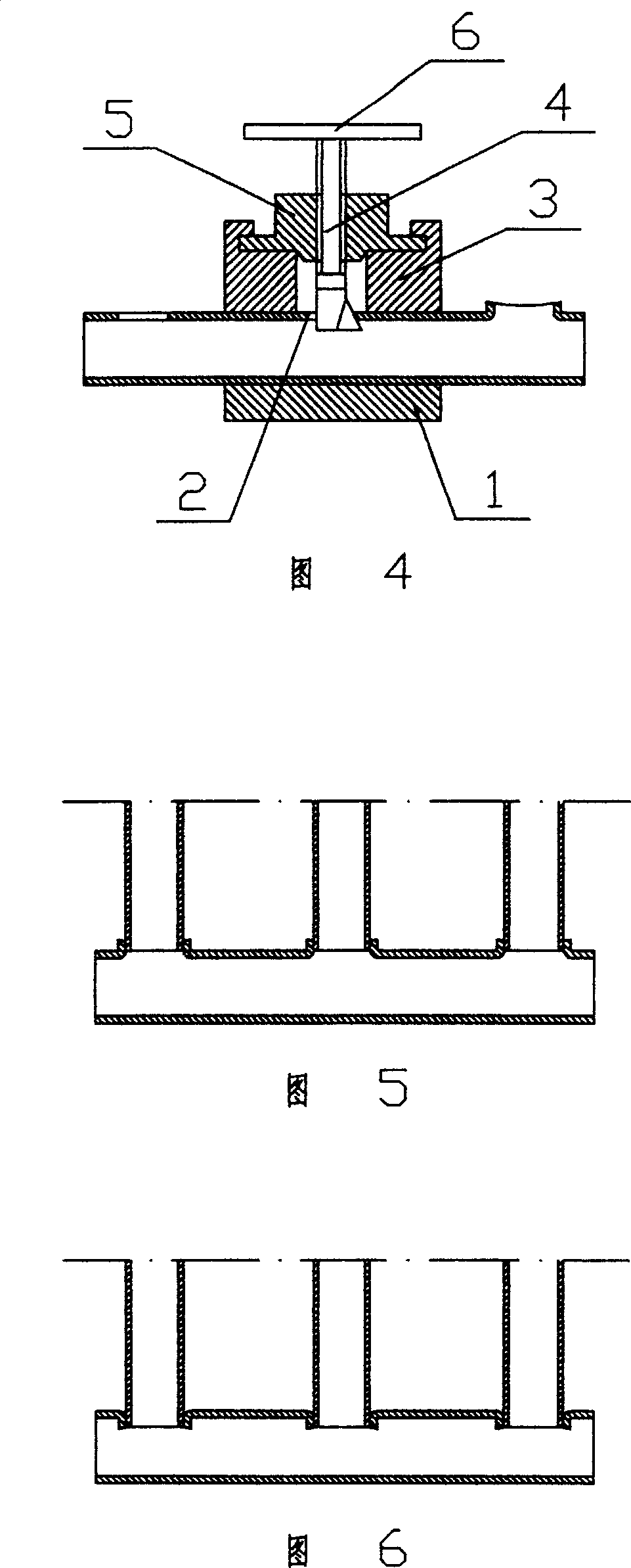
As shown in Figure 5, due to the reason of the inner flanging, the circulation water chamber of the main pipe of the inner flanging is not smooth, which increases the resistance of the water circulation and increases the load of the heat pump; while the circulation of the main pipe of the outer flanging The water cavity and the water flow channel are relatively smooth, but the flanging process is relatively complicated, and the traditional process of inner mold and outer mold is often used, and the inner mold must be inserted into the thin-walled tube, so the production efficiency is difficult to improve

Method used


Image

  • Flanging arrangement for wall hole of thin metal pipe
  • Flanging arrangement for wall hole of thin metal pipe

Examples


Embodiment 1

[0014] Embodiment 1: As shown in Fig. 1, Fig. 2 and Fig. 3, the flanging device of the thin metal pipe wall hole includes a clamp 1 for clamping the thin metal pipe, and the flanging die corresponding to the thin metal pipe wall hole 2 3. The flanging cutter 4 that can be inserted into the hole from the outer flanging mold 3 and the thin metal pipe wall hole 2, and the power device that drives the flanging cutter 4 to work, and the flanging edge 41 of the flanging cutter 4 is arranged on On one side of the handle 42, the cross-section of the flanging edge 41 gradually becomes larger along the eccentricity of the axis of the handle 42 from top to bottom, and the distance from the far end of the outer edge at the maximum cross-section of the flanging edge 41 to the axis of the handle 42 is The distance is greater than the radius of the unflange pipe wall hole, and the diameter of the circumscribed circle of the maximum cross section of the flanging edge 41 and the cross section o...

Embodiment 2

[0017] Embodiment 2: The flanging tool of this embodiment is exactly the same as that of Embodiment 1. The difference lies in the power device that drives the flanging tool to work. As shown in Figure 4, the power device includes On the mold 3 and be provided with the tool holder 5 of internally threaded hole, in the internally threaded hole of knife holder 5, the handle of a knife 42 that outer surface is provided with screw thread is installed, and the outer end of handle of a knife 42 is fixedly provided with rotary handle 6.

[0018] The technical solution of this embodiment is a manual processing method, and its working process is as follows: first, the clamp 1 clamps the thin-walled metal pipe with the hole processed, the thin metal pipe wall hole 2 is facing the outward flanging mold 3, and first the flanging tool The head of 4 is inserted into the thin metal tube wall hole 2, and the knife holder 5 is clamped on the outer flanging mold 3. At this time, the axis of the f...


PUM


Abstract

The invention discloses flanging device for thin metal pipe wall hole, which comprises clamp used to hold thin metal pipe, corresponding flanging mould, flanging cutter that can insert from flanging mould and wall hole to hole inside, power driver for flanging cutter; set flanging blade on one side of knife handle with eccentric of cross section larger along handle axis, and the distance from promote end of out margin of the maximum section to handle axis is larger than the radius of wall hole, the circumcircles of the maximum section and handle section are less than diameter of wall hole. This invention cancels inner mould, with simple technique, and improves greatly the work efficiency.

Description

technical field [0001] The invention relates to a processing device, in particular to a device for flanging the edge of a hole on the wall of a thin-walled metal pipe outward. Background technique [0002] At present, the water chamber of the copper-aluminum composite radiator adopts thin-walled copper tubes. During the processing, it is necessary to process many holes for connecting gas or liquid on the copper tubes, and weld connecting tubes between the holes opposite to the two main pipes. for heat exchange. In order to improve the welding strength, it is required to turn the edge of the hole inward or outward. As shown in Figure 5, due to the reason of the inner flanging, the flow channel of the water flow cavity of the main pipe with the inner flanging is not smooth, which increases the resistance of the water circulation and increases the load of the heat pump; while the circulation of the main pipe with the outer flanging The water cavity and the water flow channel ...

Claims


Application Information

Patent Timeline
Patent Type & Authority Patents(China)
IPC IPC(8): B21D19/12
Inventor 夏纪运宗涛
Owner 夏纪运
Learn More