
Method and device for eliminating seam between spliced display screens

A technology of display screen and seam position, which is applied to static indicators, instruments, calculations, etc., can solve the problems of reducing seam width, reducing portability, and high price, and achieves simple implementation, considerable economic benefits, and eliminates patchwork effect

Inactive Publication Date: 2008-02-06
LENOVO (BEIJING) CO LTD
View PDF6 Cites 0 Cited by
  • Summary
  • Abstract
  • Description
  • Claims
  • Application Information

AI Technical Summary

Problems solved by technology

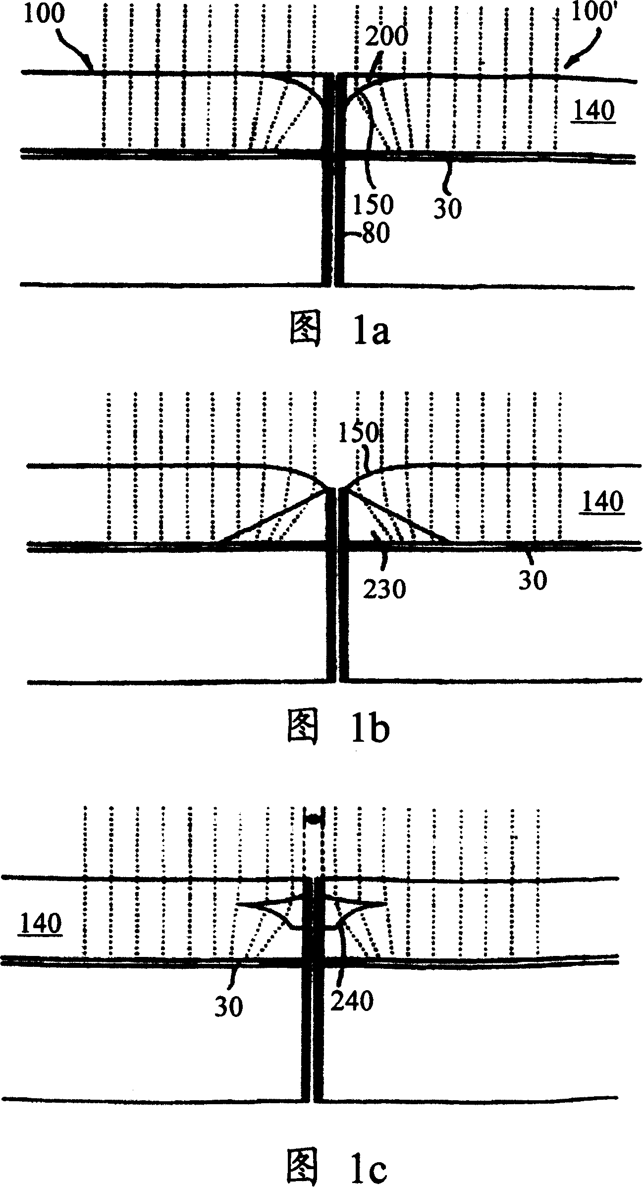
[0011] (1) This solution can only reduce the width of the patchwork, but cannot completely eliminate the patchwork; after adopting this solution, the edge of the display screen can still be seen, and the thickness of the formed patchwork is about 1 mm, which is suitable for large screens. The display is barely acceptable, but it is difficult to accept the splicing of small screens of portable devices. The performance is as follows: because small screen splicing is generally done by portable devices, and the user's eyes are usually closer to the display screen of the portable device , therefore, even if there is a little gap, it will be very obvious, which will damage the image quality and cause strong dissatisfaction among users;
[0012] (2) With this solution, the thickness of the optical glass mirror placed on the display screen is relatively large, which will increase the volume and quality of the display screen, thereby reducing its portability; for example, if two LCDs are combined, the seam width is 10 mm, the thickness of the optical glass above is 25 mm, and the optical glass of this thickness will significantly increase the volume and quality of the display screen, making it unfavorable to carry;
[0013] (3) Since the solution needs to compress and enlarge the edge of the image, it will cause damage to the image itself;
[0017] (1) In order to obtain proper magnification, the Fresnel magnifier must leave a certain distance from the display 20, otherwise the image cannot be enlarged, which will cause the display to be relatively thick, thereby increasing the volume of the display screen, making the portability of the equipment formed by this method reduce;
[0018] (2) In order for the Fresnel magnifying glass to bend the light passing through the magnifying glass and produce diffraction phenomenon, thereby forming the effect of the magnifying glass, the surface must be covered with small zigzag concentric circle stripes, which will cause certain damage to the image , thereby reducing the image quality;
[0019] In addition, the processing cost of the Fresnel magnifying glass is relatively high, and the high price affects the practical application

Method used


Image

  • Method and device for eliminating seam between spliced display screens
  • Method and device for eliminating seam between spliced display screens
  • Method and device for eliminating seam between spliced display screens

Examples


Embodiment 1

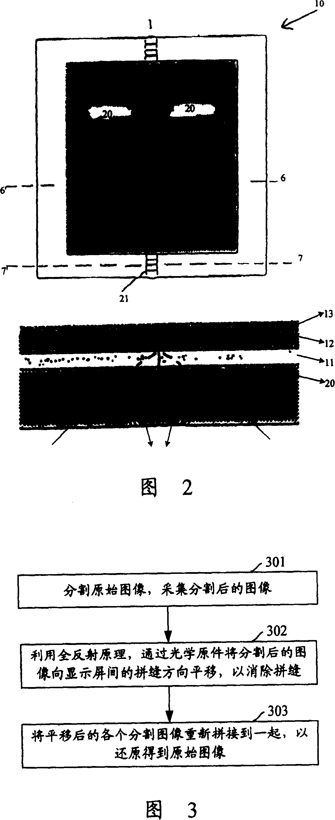
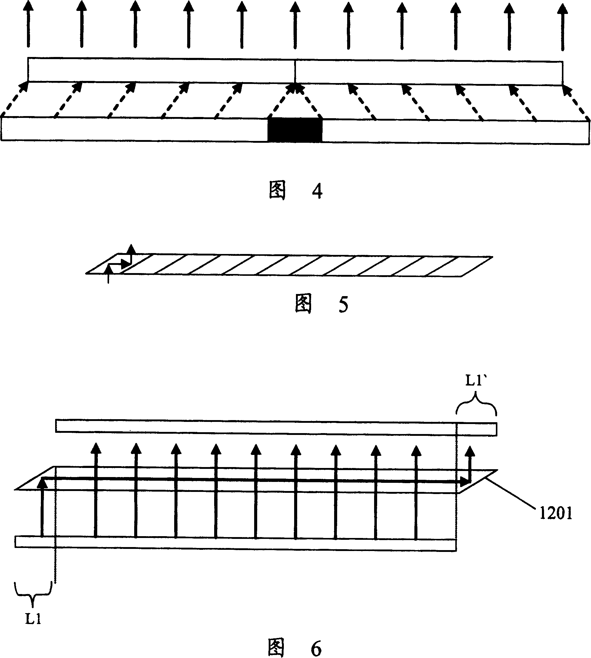
[0077] Referring to Fig. 4, Fig. 5 and Fig. 10, in this embodiment, an optical lens composed of each translation unit is used as an image translation module, wherein each translation unit can make use of the principle of total reflection to translate the incident light to the seam position; the image The acquisition module is used to segment and acquire the original image in units of the cross-sectional shape of the translation unit, and transmit the acquired segmented image to the corresponding translation unit, and each translation unit in the image translation module is used to separate each segmented image Translating to the seam position, the image restoration module is used to receive each segmented image output by each translation unit after translation, and merge these segmented images together to restore the original image; wherein, the image acquisition module can be realized by using a software module, Optical elements can also be used to realize the image acquisitio...

Embodiment 2

[0079] Referring to Figure 6, the integral optical element with translation units on both sides is used as the image translation module. The translation unit can use the principle of total reflection to translate the incident light to the seam position. The image acquisition module is used to cut the image and join the cut parts To the side of the image away from the seam of the display screen, the image translation module is used to translate the image of the cut part to the seam position, and the image restoration module is used to merge the shifted cut image with the uncut image to restore the original image Wherein, the image acquisition module and the image restoration module can be realized respectively by using software modules, and these two modules can also be realized by using optical elements, which does not affect the realization of the present invention;

[0080] Wherein, in Embodiment 1 and Embodiment 2, the image restoration module may further include a filter pr...

Embodiment 3

[0082] Referring to Fig. 9, in the embodiment, the end of each optical fiber close to the display screen is used as an image acquisition module, and each pixel point of the image is obtained by using the end; the transmission part of each optical fiber is used as an image translation module, It is used to transmit each pixel of the image to the seam position; the end of each optical fiber away from the display screen is used as an image restoration module, which is used to output the pixels transmitted by each optical fiber to form an original image;

[0083] In other embodiments of the present invention, the optical fiber device composed of the entire inclined optical fiber shown in Fig. 9 can also be used as the image translation module, and the image acquisition module and the image restoration module can be realized by using software modules respectively, or by using optical The components implement these modules and do not affect the implementation of the present invention...


PUM


Abstract

The method includes steps: (1) collecting original images, which are suitable for image shift in subsequent step (2); (2) shifting the collected images to position of edge joint; (3) restoring the shifted images to original images. The invention also provides device for eliminating edge joint between scabbed display screens. The device includes image collection module, module for shifting original image, and image restoring module. The image collection module is in use for collecting original images, and sends the collected images to the module for shifting original image. The module for shifting original image is in use for shifting the received image to position of edge joint so that the shifted images can cover the edge joint. Receiving the shifted images from the module for shifting original image, the image restoring module restores the shifted images to the original images.

Description

technical field [0001] The invention belongs to the technical field of image display, and in particular relates to a method and a device for eliminating seams between spliced ​​display screens. Background technique [0002] At present, with the continuous advancement of electronic information technology, more and more computers are developing in the direction of miniaturization. At the same time of miniaturization, the computer's ability to process data has also been strengthened. The types of data it can process is also becoming more widespread. People can use small portable computers to complete large-scale data processing, storage, and collection work, which greatly facilitates people's daily work and life. For example, a notebook computer may be used to process stock information, map data, and image data, and display corresponding content on a display screen according to the processing results. However, due to the miniaturization of the computer, its display screen wil...

Claims


Application Information

Patent Timeline
Patent Type & Authority Patents(China)
IPC IPC(8): G02B3/00G02B6/00G02F1/133G06F1/00
Inventor 李众庆
Owner LENOVO (BEIJING) CO LTD
Learn More