
Optical film thickness monitoring system

A technology of optical film thickness and monitoring system, applied in optics, optical components, optical devices, etc., can solve the problem of inability to eliminate noise, and achieve the effect of flexible and convenient use, elimination of influence, high reliability and accuracy

Inactive Publication Date: 2008-01-30
SHANGHAI INST OF OPTICS & FINE MECHANICS CHINESE ACAD OF SCI
View PDF4 Cites 1 Cited by
  • Summary
  • Abstract
  • Description
  • Claims
  • Application Information

AI Technical Summary

Problems solved by technology

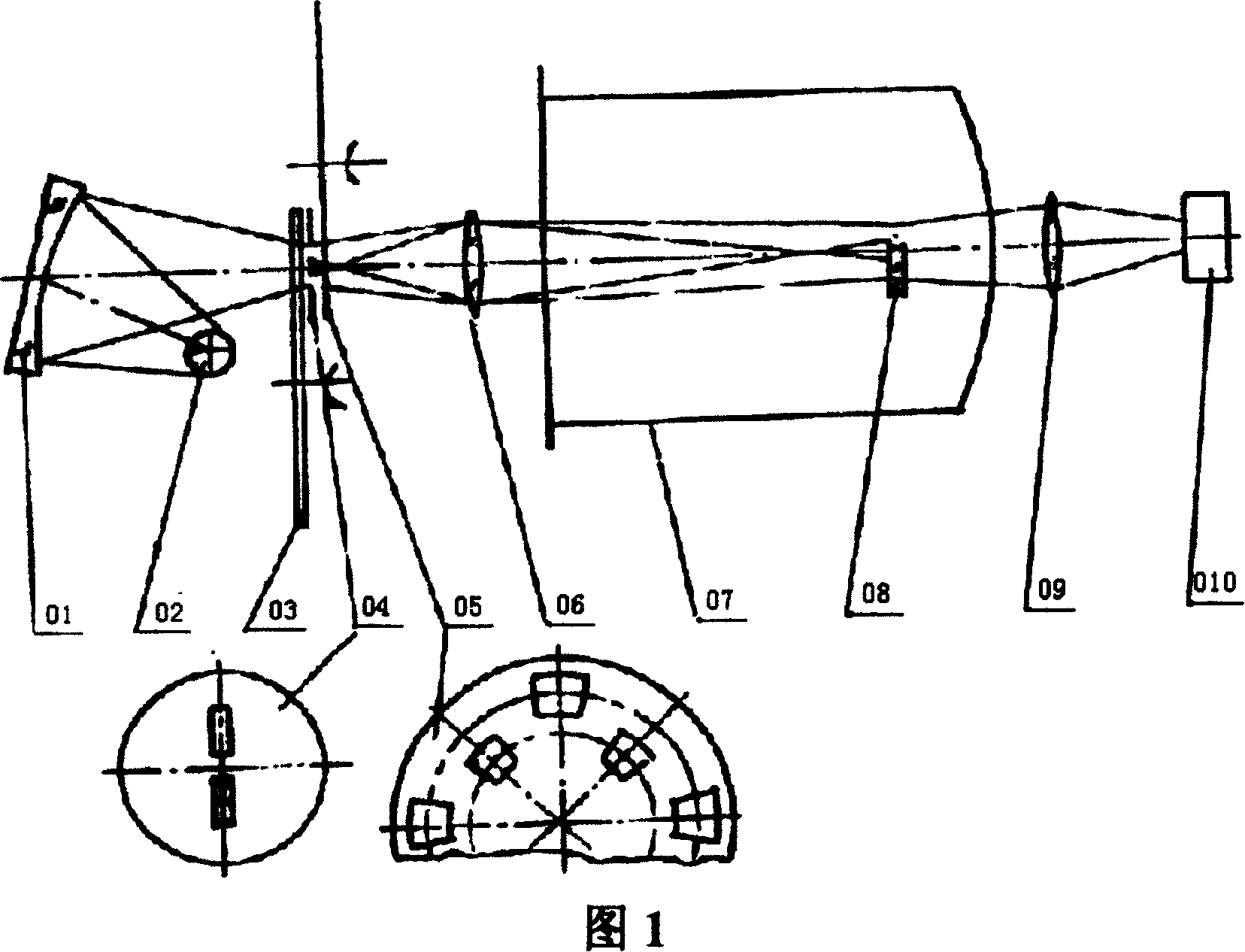
The vertical transmissive double-beam optical system cited above can only monitor the signal of the transmitted light, and the above-mentioned system cannot eliminate the noise whose frequency is inconsistent with the frequency of the incident light. In addition, the equal double-aperture diaphragm 04 needs to be imaged on the monitoring film 08 through the lens 06 Therefore, there are strict requirements on the distance between the equivalence double-aperture diaphragm 04, the lens 06, and the monitoring piece 08, and the measurement beam is required to pass through the monitoring piece 08, and the reference beam is to pass by the side of the monitoring piece 08. The size requirements of Circum 04 and Monitoring Film 08 are very high

Method used


Image

  • Optical film thickness monitoring system
  • Optical film thickness monitoring system
  • Optical film thickness monitoring system

Examples


Embodiment Construction

[0025] The present invention will be further described below in conjunction with the embodiments and accompanying drawings.

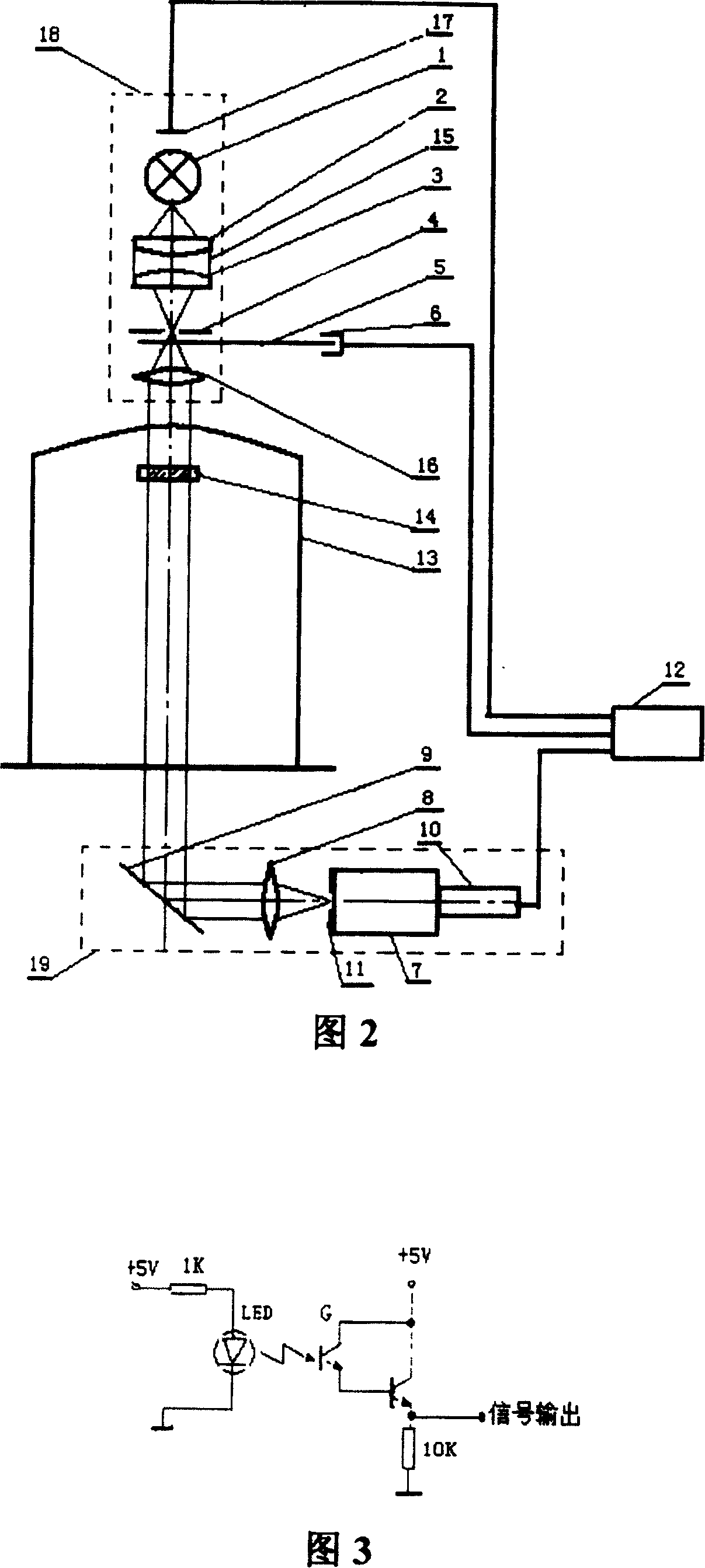
[0026] Please refer to FIG. 2 first. FIG. 2 is a schematic structural diagram of a transmissive optical film thickness monitoring system according to Embodiment 1 of the present invention. Four parts of system 19 and lock-in amplifier 12:

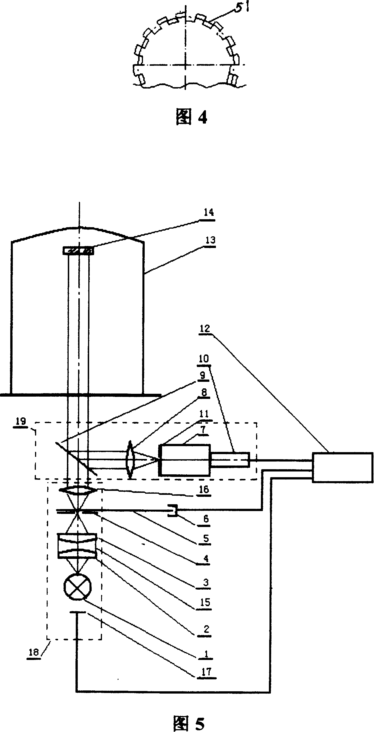
[0027] Described light source emission system 18 is assembled into one by the light source 1 with photocell 17 and the condenser lens 15 that is arranged successively along the advancing direction of the light beam that this light source 1 sends, diaphragm 4, single-row hole reticle 5 and collimator mirror 16, The aperture hole of the aperture 4 is placed at the focal point of the condenser 15, and the single-row aperture modulation disc 5 is provided with an optical switch 6, and the modulation aperture 51 on the periphery of the single-row aperture modulation disc 5 is close to the aperture 4 and located on the li...


PUM


Abstract

The optical film thickness monitoring system for real-time monitoring of film thickness during plating film features its structure including four parts of light source emitting system, monitoring sheet, signal receiving system and phase-locking amplifier. The light source emitting system consists of light source with photocell and light focusing lens, diaphragm, single hole row reticle and collimating lens arranged successively in the light beam direction. The signal receiving system is one concentric system comprising refracting element, convergent lens, monochromator and photoelectric multiplier set successively. The optical film thickness monitoring system may be either vertical transmitting one or reflecting one, and has convenient installation and change and high monitoring precision.

Description

technical field [0001] The invention relates to film coating, in particular to an optical film thickness monitoring system for real-time monitoring of film thickness in the film coating process. Background technique [0002] The optical film thickness monitoring system is an optical system that monitors the thickness of the film during the vacuum coating process. The existing system for monitoring the thickness of the optical film is a vertical transmission optical system (85101725, published on October 7, 1987). Figure 1 is its optical path As shown in the figure, a first-class double-aperture diaphragm 04 is placed behind the angle-variable filter 03 or the exit slit of the monochromator, and the common center line of the double holes passes through the rotation axis of the angle-variable filter 03 (optical axis) vertically. ). The reflective condenser 01 images the light source 02 on the equal double-aperture diaphragm 04, the measuring beam and the reference beam emerge...

Claims


Application Information

Patent Timeline
Patent Type & Authority Patents(China)
IPC IPC(8): G02B27/00G01B11/06C23C14/52C23C14/54
Inventor 朱美萍易葵郭世海邵建达王丹申雁鸣傅小勇毕军
Owner SHANGHAI INST OF OPTICS & FINE MECHANICS CHINESE ACAD OF SCI
Learn More