
Plastic filtering board or board forming process

A molding method and filter plate technology, which are used in household components, household appliances, other household appliances, etc., can solve the problems of filter plate strength and quality, unsatisfactory insulation effect of material barrels, and long moving process of material barrels. , to achieve the effect of shortening material consumption, good thermal insulation effect, and reducing the types of formulas

Active Publication Date: 2008-01-09
ZHEJIANG LONGYUAN ENVIRONMENTAL TECH CO LTD
View PDF3 Cites 4 Cited by
  • Summary
  • Abstract
  • Description
  • Claims
  • Application Information

AI Technical Summary

Problems solved by technology

[0002] At present, most of the filter plate pressing is plasticized by the screw and extruded into the insulation barrel. After weighing, it is manually transferred to the mold and then molded. The biggest defect of this method is: first, the single-screw plasticizing temperature is too high, and the material performance is greatly lost. ; Second, the thermal insulation effect of the material tank is not ideal, and the temperature is uneven; third, the moving process of the material tank takes a long time, which takes a few minutes; fourth, the filter plate is cold-separated and has many pores; Sixth, the strength and quality of the filter plate are fixed; Seventh, the degree of automation is low and the production cycle is long, especially for large-scale filter plates

Method used


Image

  • Plastic filtering board or board forming process

Examples


Embodiment 1

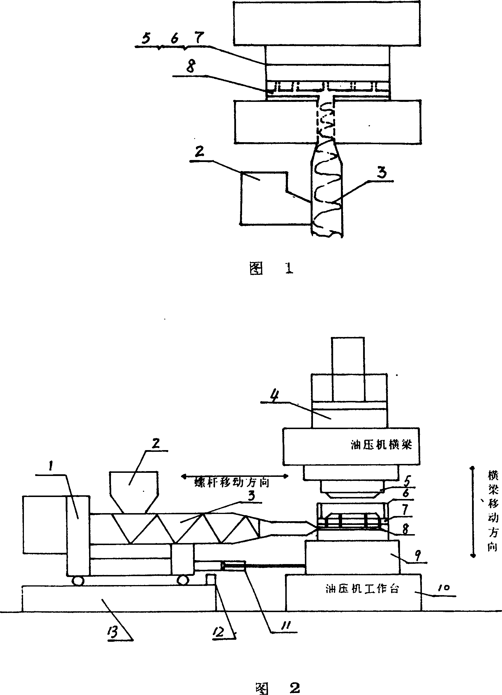
[0010] Embodiment 1: with reference to accompanying drawing 1. Plastic filter plate forming method, the hot runner port of the hot runner plastic filter plate forming mold or the hot runner plate forming mold is located on the upper part or the bottom or the side of the hot runner plastic filter plate forming mold or the hot runner plate forming mold, the injection molding mechanism of the injection molding machine The discharge port is aligned with the hot runner port. After the plastic raw material is heated and plasticized by the injection molding mechanism, the discharge port is injected into the cavity of the mold through the hot runner in the hot runner plastic filter plate forming mold or the hot runner plate forming mold, and then cooled and finalized. After the mold is opened, the filter plate or plate can be taken out. When the hot runner opening of the hot runner plastic filter plate forming mold or the hot runner plate forming mold is located on the upper part of t...

Embodiment 2

[0011] Embodiment 2: plastic filter plate forming method, the hot runner port of the hot runner plastic filter plate forming mold or the hot runner plate forming mold is located at the top or bottom or side of the hot runner plastic filter plate forming mold or the hot runner plate forming mold, and the injection molding mechanism The outlet of the outlet is aligned with the hot runner mouth, the hydraulic press is closed, the plastic raw material is heated and plasticized by the injection molding mechanism, and the outlet is injected into the cavity of the mold through the hot runner in the hot runner plastic filter plate forming mold or the hot runner plate forming mold After internal forming, cooling and setting, the hydraulic press opens the mold to take out the filter plate or plate. The filter plate or plate forming mold is located in the hydraulic press and is clamped and opened by the hydraulic press. The hot runner device is located on the upper or bottom or side of th...


PUM


Abstract

A process for preparing the plastic filter plate or plastic plate features that its mould is controlled by hydraulic press, its heat channel is positioned at the bottom of lower mould and communicated with said lower mould, and the plasticized plastics is injected in said mould via heat channel.

Description

Technical field: [0001] The invention relates to a method for forming a filter plate of a filter press, which belongs to the field of filter plate manufacturing of a filter press. Background technique: [0002] At present, most of the filter plate pressing is plasticized by the screw and extruded into the insulation barrel. After weighing, it is manually transferred to the mold and then molded. The biggest defect of this method is: first, the plasticizing temperature of the single screw is too high, and the loss of material properties is large. ; Second, the thermal insulation effect of the material tank is not ideal, and the temperature is uneven; third, the moving process of the material tank takes a long time, which takes a few minutes; fourth, the filter plate is cold-separated and has many pores; Sixth, the strength and quality of the filter plate are not changed; Seventh, the degree of automation is low and the production cycle is long, especially for large-size filter...

Claims


Application Information

Patent Timeline
Patent Type & Authority Patents(China)
IPC IPC(8): B29C45/27B29L31/14
Inventor 朱兴源徐美良韩金良彭云秋
Owner ZHEJIANG LONGYUAN ENVIRONMENTAL TECH CO LTD
Learn More