
Optical pickup apparatus, optical recording and reproducing apparatus and optical recording and reproducing method

A technology for optical pickup and optical recording, which is applied to recording/reproducing by optical methods, optical recording heads, data recording, etc., and can solve the problems of difficulty in adjusting the spot size, difficulty in reducing the thickness of the device, and reducing the size of the device.

Inactive Publication Date: 2007-11-21
SONY CORP
View PDF5 Cites 0 Cited by
  • Summary
  • Abstract
  • Description
  • Claims
  • Application Information

AI Technical Summary

Problems solved by technology

[0009] However, as for the method of adjusting the direction of the beam intensity distribution of the far-field pattern of light emitted from the above-mentioned semiconductor laser by rotation of the semiconductor laser, when the semiconductor laser is rotated without a degree of freedom, due to, for example, a thin optical pickup device The thickness of semiconductor lasers that have been put into practical use and housed in packages is reduced in the direction perpendicular to the active layer thereof, so it is difficult to rotate the semiconductor lasers and thus it is difficult to adjust the spot size on a disk-shaped optical recording medium
[0010] In addition, if a relatively expensive beam profile converter such as an anamorphic prism is used, the cost inevitably increases, and problems arise in which it is difficult to downsize the device and reduce the thickness of the device

Method used


Image

  • Optical pickup apparatus, optical recording and reproducing apparatus and optical recording and reproducing method
  • Optical pickup apparatus, optical recording and reproducing apparatus and optical recording and reproducing method
  • Optical pickup apparatus, optical recording and reproducing apparatus and optical recording and reproducing method

Examples


Embodiment Construction

[0036] Examples of the present invention will be described below, but needless to say, the present invention is not limited to the following examples.

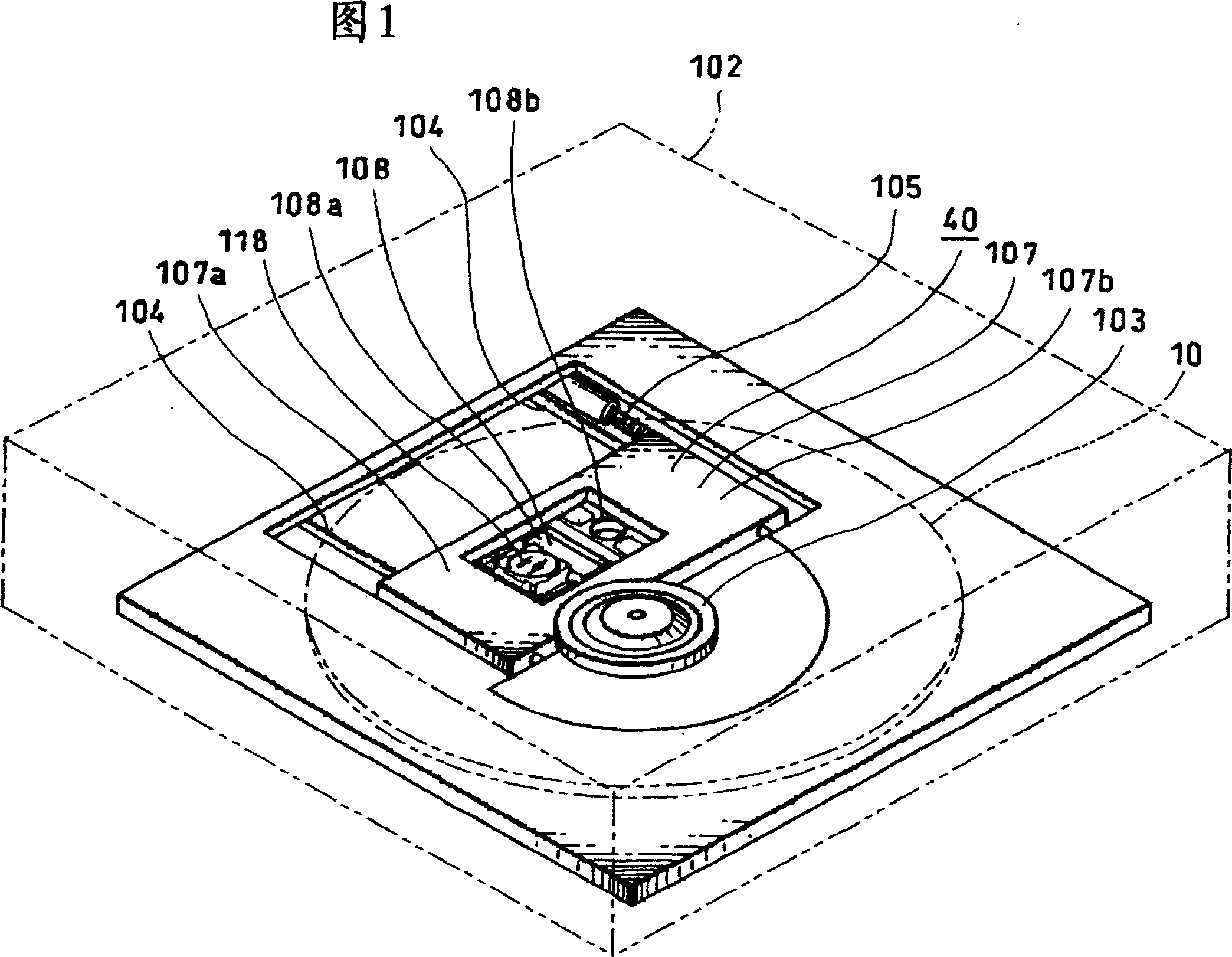
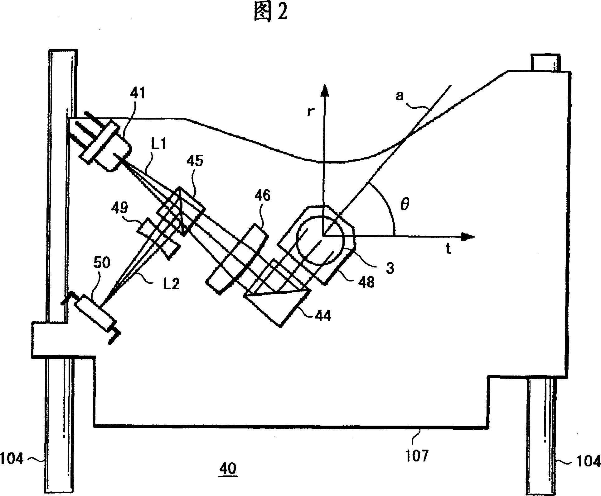
[0037] First, an example of an optical recording and reproducing apparatus and an optical pickup apparatus will be described with reference to the schematic layout diagrams of FIGS. 1 and 2 .

[0038]As shown in FIG. 1, such an optical recording and reproducing apparatus 100 includes a housing 102 in which predetermined components and corresponding mechanisms are arranged. This housing 102 has an insertion groove formed therein and into which a disc-shaped optical recording medium 10 is inserted and ejected, although not shown.

[0039] A spindle motor (not shown) for moving the optical recording medium 10 is fixed to a chassis (not shown) inside the casing 102, and for example, a disk stage 103 is fixed to the motor shaft of the spindle motor.

[0040] Parallel guide shafts 104 and 104 are fixed to a chassis (not shown) and ...


PUM

PropertyMeasurementUnit
wavelengthaaaaaaaaaa

Abstract

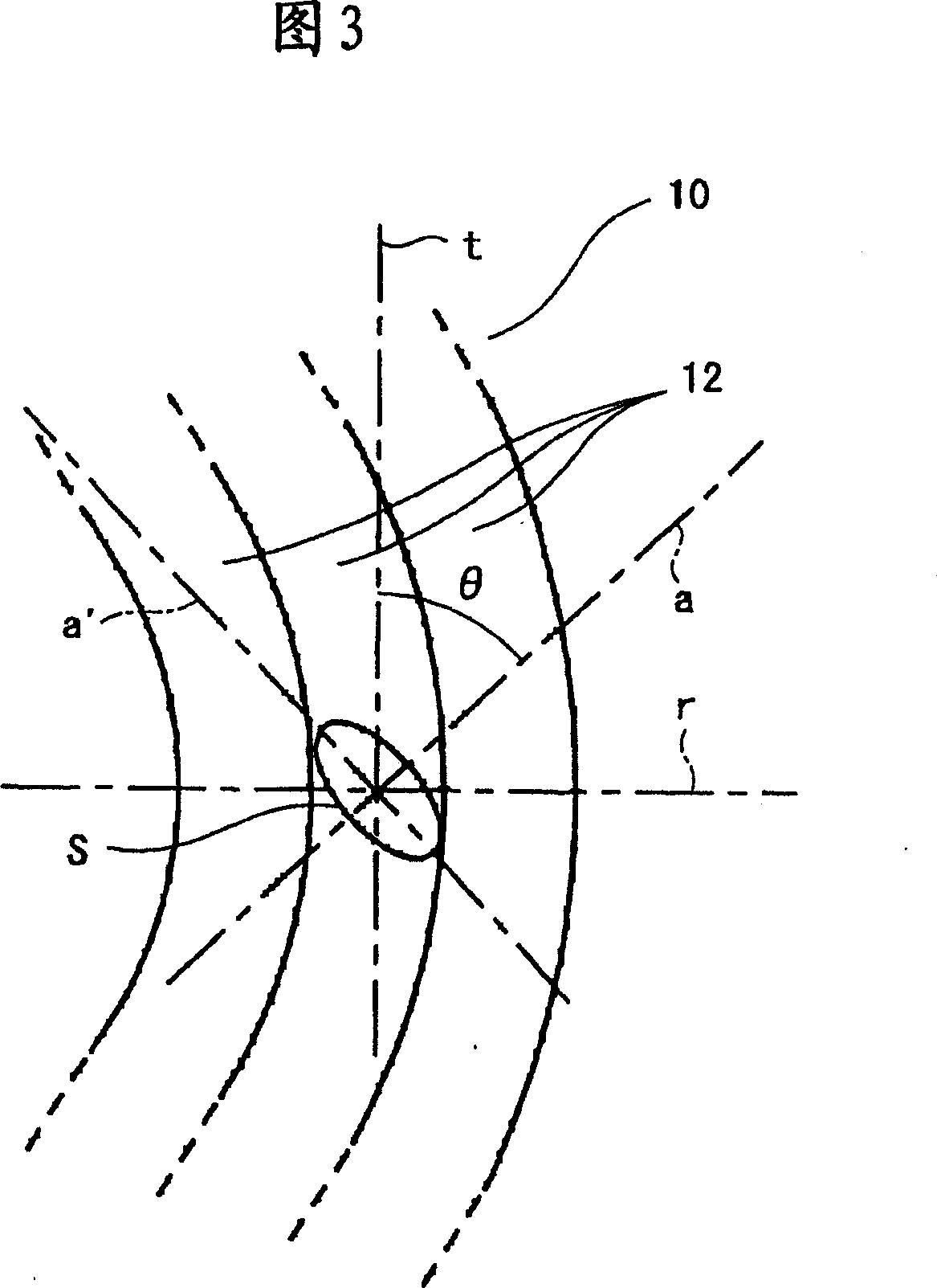
An optical pickup apparatus comprising: a semiconductor laser for emitting laser light with a wavelength of at least from 400 nm to 415 nm and of which plane parallel to an active layer is located substantially in parallel to the recording surface of an optical recording medium; and a reflection surface for reflecting laser light emitted from said semiconductor laser in the direction substantially perpendicular to the recording surface of said optical recording medium, said laser light being irradiated on said optical recording medium through an objective lens to record and / or reproduce said optical recording medium, wherein an angle theta formed between the direction of rays of light introduced into said reflection surface from said semiconductor laser and the direction in which recording tracks of said optical recording medium are extended is selected so as to satisfy: 45 DEG <= theta < 90 DEG. The invention hold an excellent recording and reproducing characteristic by emitting a beam spot to a recording track in an optimum shape, and an optical recording medium includes an optical recording medium of a BD (Blu-ray Disc) type configuration.

Description

[0001] Cross References to Related Applications [0002] The present invention contains subject matter related to Japanese Patent Application JP 2004-225833 filed in the Japan Patent Office on Aug. 2, 2004, the entire content of which is hereby incorporated by reference. technical field [0003] The present invention relates to an optical pickup device, an optical recording and reproducing device, and an optical recording and reproducing method suitable for use in recording and reproducing a high recording density optical recording medium having a very narrow track pitch. Background technique [0004] In recent years, in terms of optical recording media, various optical recording media having different recording densities have been developed. In terms of disk-shaped optical recording media, CD (Compact Disc) in which laser light having a wavelength near 780 nm is suitable, DVD (Digital Versatile Disc) in which laser light having a wavelength near 660 nm is suitable, laser li...

Claims


Application Information

Patent Timeline
Patent Type & Authority Patents(China)
IPC IPC(8): G11B7/12G11B7/135
CPCG11B7/1398G11B7/127G11B7/1362
Inventor 山本健二佐藤克利西纪彰金谷绿莳田真哉
Owner SONY CORP
Learn More