
Patsnap Eureka
For R&D, Patsnap Eureka makes reading and utilizing patents & technical documents easy.
Patsnap Eureka AIR
Designed for self-driven R&D workflows. Generate viable solutions, solve complex R&D challenges, empower your innovation with AI.

Patsnap Eureka Materials
Designed for material experts only. Revolutionize your material R&D, from search, analyze, to developing new materials.

TechResearch
Generate reliable direction feasibility study reports for your R&D in just a few steps.

TechSeek
Discover and master advanced knowledge NOW. Basics, ideas, possibilities, all at once.

TechMind
As an expert in R&D Theories, TechMind can generates customized viable solutions instantly.

TechRisk
Analyze your overall solution with one click, know your potential R&D risks in advance.

TechMonitor
Get weekly tech updates, stay abreast of the latest tech innovations and key insights.
Method for improving refractive index distribution of self-focusing lens
A technology of refractive index distribution and self-focusing lens, which is applied in the field of improving the refractive index distribution of self-focusing lens, and can solve the problems of large aberration of self-focusing lens, large exit spot size, and affecting the quality of self-focusing lens.
- Summary
- Abstract
- Description
- Claims
- Application Information
AI Technical Summary
Problems solved by technology
Method used
Image

Examples
Embodiment 1
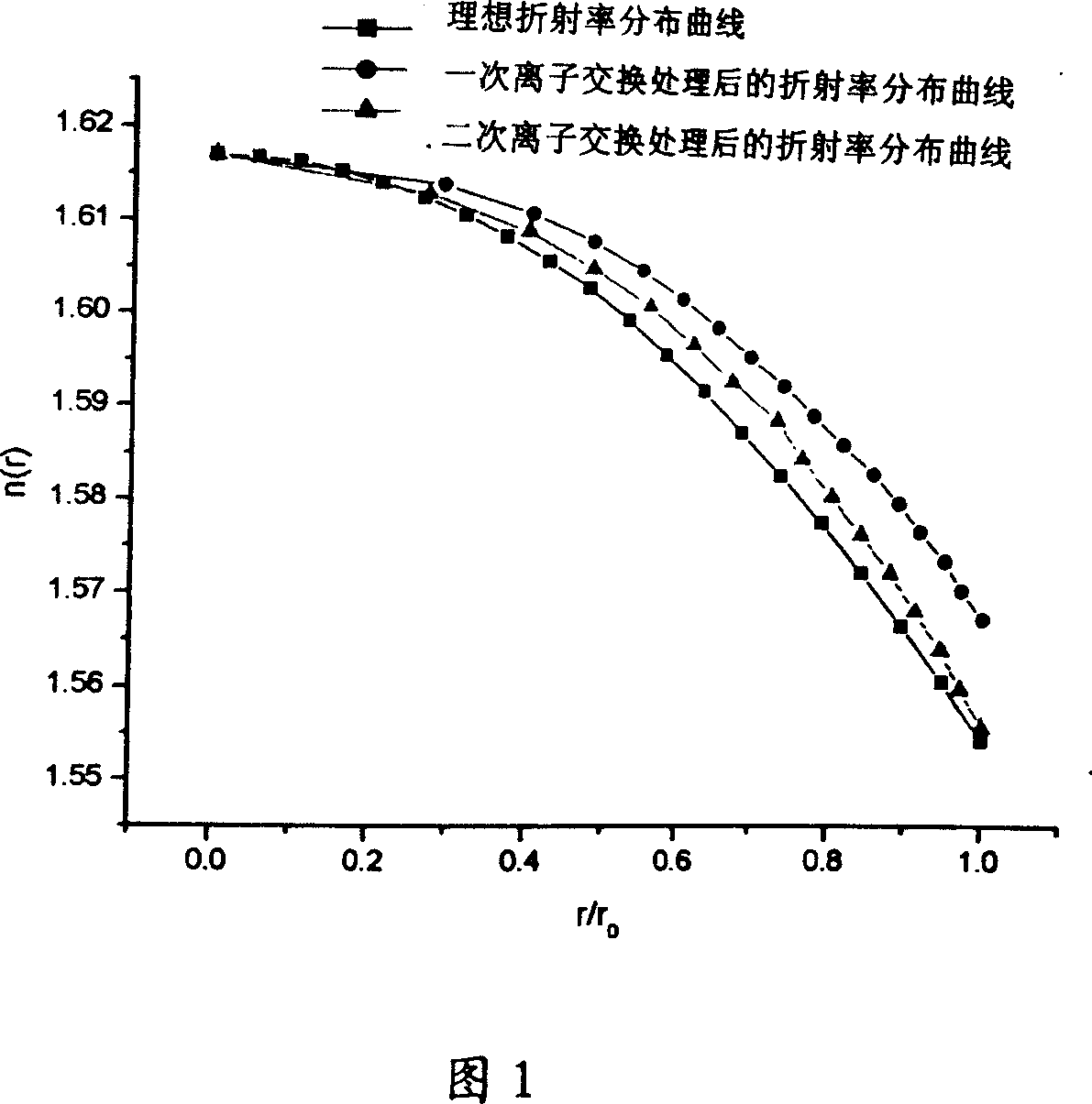
[0020] Example 1: Referring to Figure 1, the refractive index distribution of the self-focusing lens sample NO 01 after the first ion exchange was measured by thin-section interferometry, and the distortion and spherical aberration of the sample were measured. The measurement result shows that the sample is negative spherical aberration and barrel-shaped Distortion, the refractive index distribution of its edge is higher than the ideal refractive index distribution. In order to improve the refractive index distribution at the edge, the purpose of the second ion exchange treatment is to reduce the refractive index at the edge of the self-focusing lens to make it closer to the ideal refractive index distribution. Therefore, in the secondary ion exchange, the molten salt used is a mixed salt of 3% NaNO3 and 97% KNO3, and the ion exchange temperature is 530°C±0.5°C. In order to only correct the refractive index distribution at the edge of the lens, the secondary ion exchange The t...
Embodiment 2
[0021] Example 2: Except that the secondary ion exchange time was changed to 25 minutes, the others were the same as in Example 1. For the self-focusing lens sample NO 02 after the secondary ion exchange, the refractive index distribution and aberration characteristics were measured, and the measurement The results show that the barrel distortion is reduced from the original 0.160 to 0.073, and the longitudinal spherical aberration is reduced from the original 0.210 to 0.190, which obviously improves the refractive index distribution and aberration characteristics of the edge of the self-focusing lens.
Embodiment 3
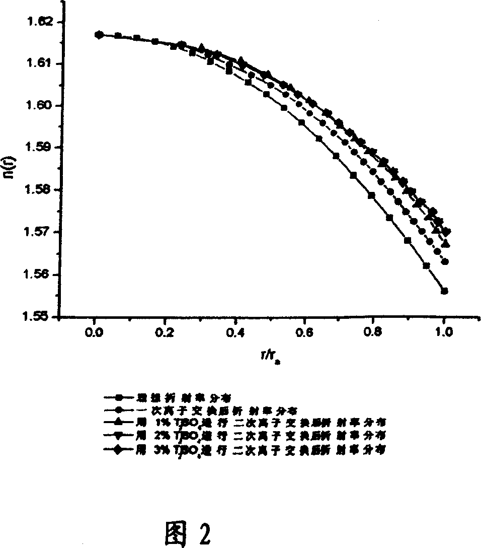
[0022] Example 3: The refractive index distribution of the self-focusing lens sample NO 01 after the first ion exchange was measured by thin-section interferometry, and the distortion and spherical aberration of the sample were measured. The measurement results showed that the sample had negative spherical aberration, barrel distortion, and its edge The refractive index profile of the part is higher than the ideal refractive index profile. In order to improve the refractive index distribution at the edge, the purpose of the second ion exchange treatment is to reduce the refractive index at the edge of the self-focusing lens to make it closer to the ideal refractive index distribution. Therefore, in the secondary ion exchange, the molten salt used is 2% NaNO 3 with 98% KNO 3 The mixed salt, the ion exchange temperature is 530°C±0.5°C, in order to only correct the refractive index distribution at the edge of the lens, the secondary ion exchange time is 30 minutes. For the two ...
PUM
 Abstract
Description
Claims
Application Information
 - R&D Engineer
- R&D Manager
- IP Professional
- Industry Leading Data Capabilities
- Powerful AI technology
- Patent DNA Extraction
Browse by: Latest US Patents, China's latest patents, Technical Efficacy Thesaurus, Application Domain, Technology Topic, Popular Technical Reports.
© 2024 PatSnap. All rights reserved.Legal|Privacy policy|Modern Slavery Act Transparency Statement|Sitemap|About US| Contact US: help@patsnap.com