Optical fibers with reduced splice loss and methods for making same

a technology of optical fibers and splice loss, applied in the field of optical fibers, can solve the problems of difficult to maintain desired performance, difficult to achieve acceptable performance for edfs, and splice loss typically 0.1-0.2 db, and achieve the effect of reducing the cutoff wavelength and increasing the fiber's refractive index volum

Active Publication Date: 2005-12-29
FURAKAWA ELECTRIC NORTH AMERICA INC
View PDF8 Cites 4 Cited by
  • Summary
  • Abstract
  • Description
  • Claims
  • Application Information

AI Technical Summary

Benefits of technology

[0010] To address such issues and others, an optical fiber in accordance with one aspect of the present invention has a core region and a volume increasing region surrounding the core. The volume increasing region is doped to increase the fiber's refractive index volume. A cutoff reduction region surrounds the volume increasing region. The cutoff reduction region is doped to reduce the fiber's cutoff wavelength, offsetting an increase in the fiber's cutoff wavelength caused by the first cladding region. An outer cladding surrounds the cutoff reduction region. According to a further aspect of the invention, the volume increasing region is doped to have a refractive index profile that is sloped to increase from the region's outer circumference towards its inner circumference. According to another aspect of the invention, the cutoff reduction region has a step refractive index profile that may comprise more than one section.

Problems solved by technology

However, it has proven to be difficult to maintain desired performance when these fibers are spliced to other fibers, particularly fibers having different modefield diameters (MFDs) and refractive index profiles (RIPs), such as a standard single mode fiber (SSMF).
It has been found that splicing an EDF to an SSMF results in a splice loss that is typically 0.1-0.2 dB higher than when other types of fiber are spliced to an SSMF.
Achieving acceptable performance for EDFs is especially challenging in an optical amplifier, where low splice loss may be required for a wide signal wavelength range.
However, it has proved difficult to use a thermal diffusion technique to obtain an RIP for the EDF with the desired degree of similarity to the RIP of the SSMF, while maintaining an acceptably low cutoff wavelength.
Further, splice loss issues are aggravated by variations in splice conditions, particularly in a volume production environment.
These variations are caused by a number of factors that may be difficult to control, including worn splice electrodes and fluctuations in current control, as well as environmental conditions, such as humidity, temperature, pressure and the like.
With current fiber designs, these variations can contribute significantly to splice loss.

Method used


Image

  • Optical fibers with reduced splice loss and methods for making same
  • Optical fibers with reduced splice loss and methods for making same
  • Optical fibers with reduced splice loss and methods for making same

Examples


Embodiment Construction

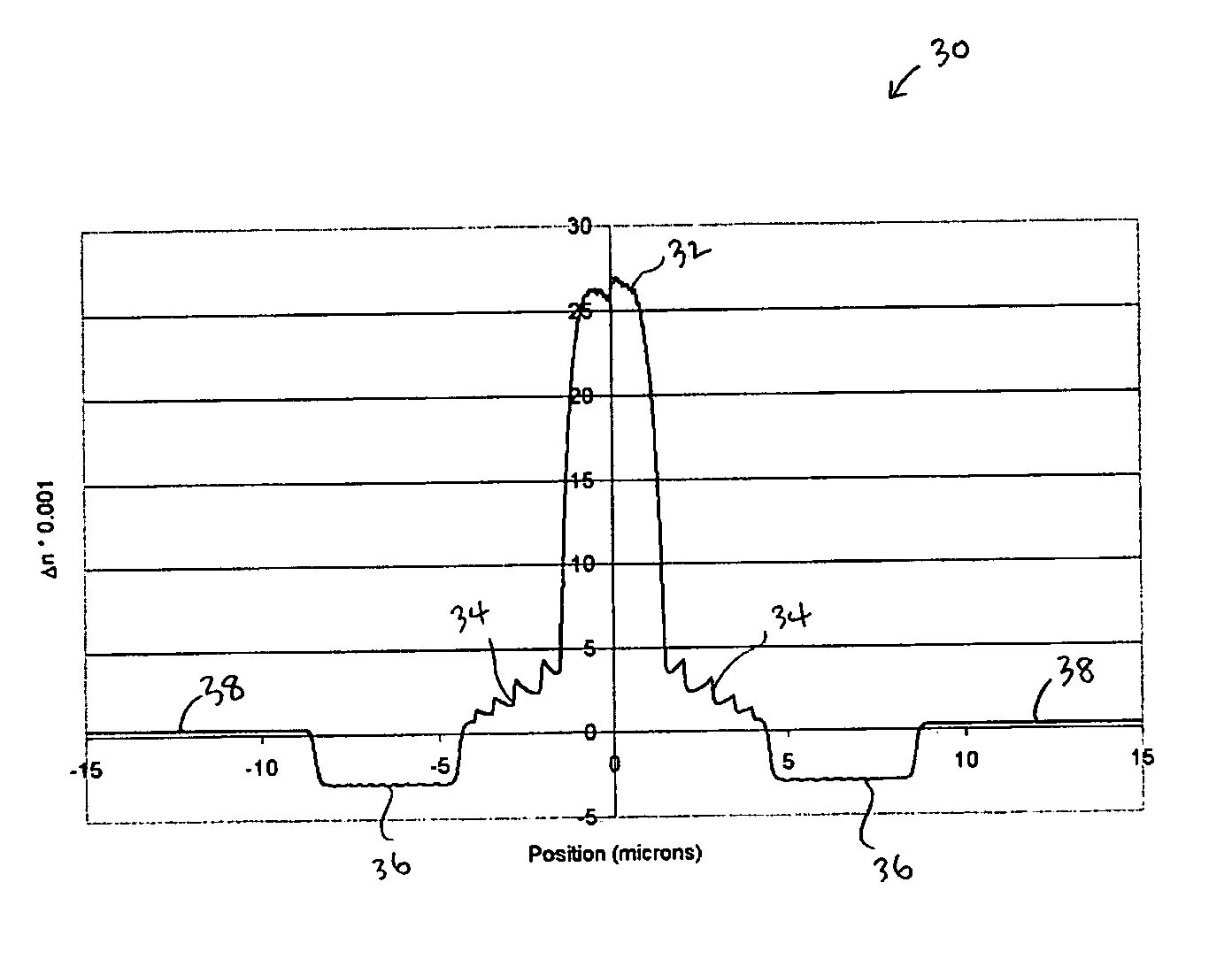
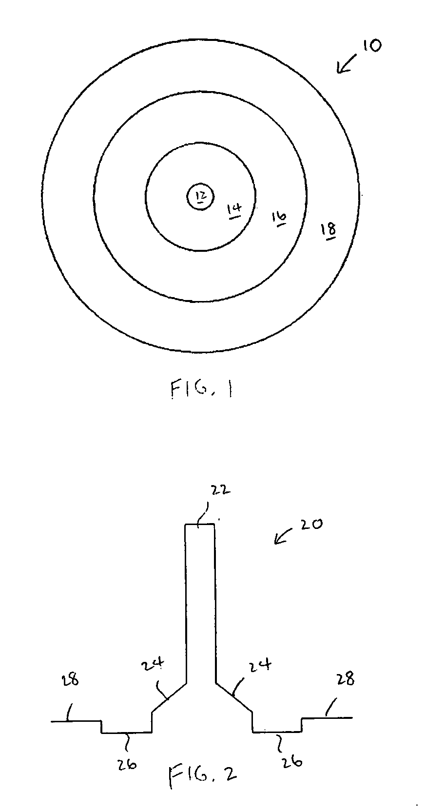
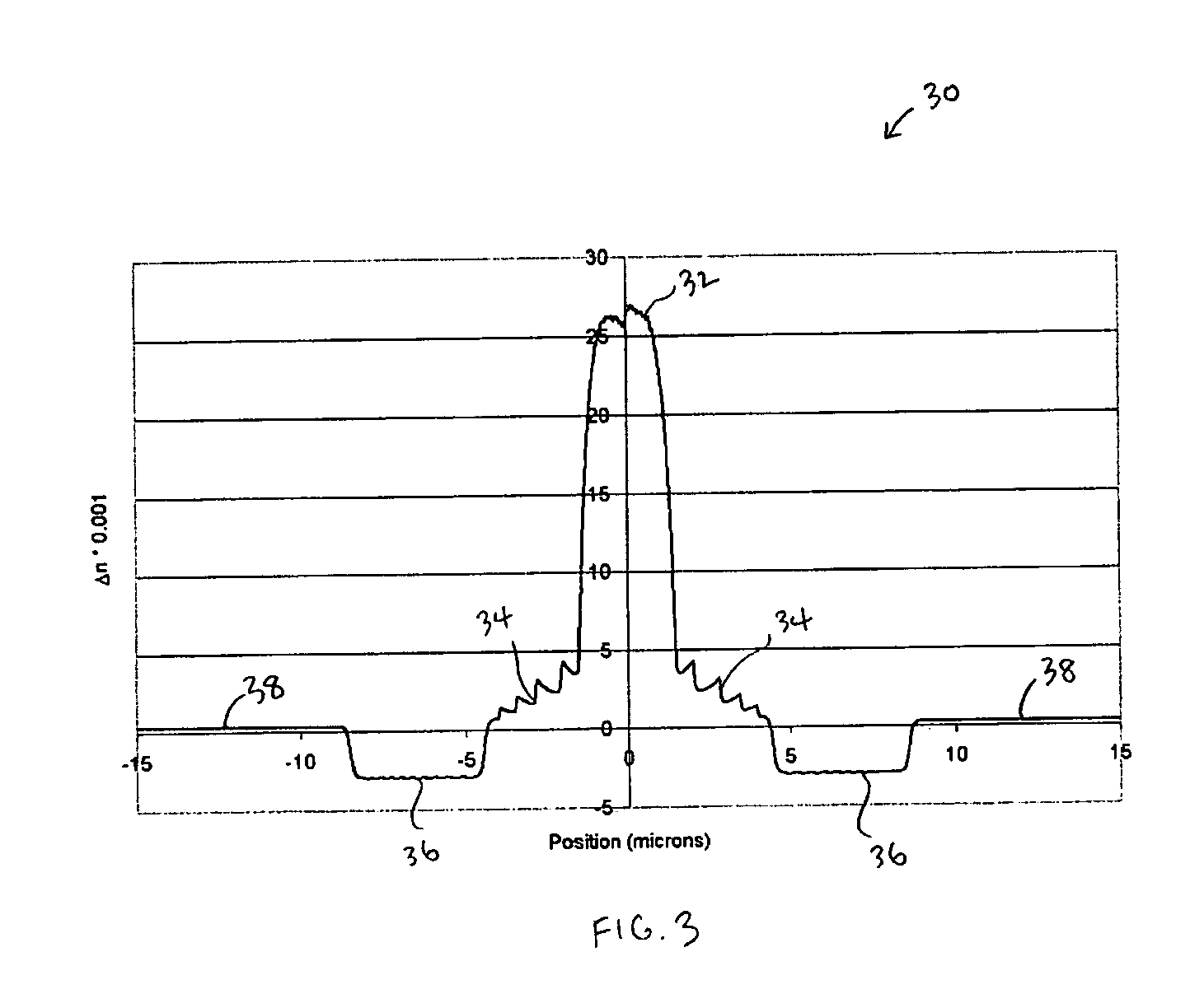
[0022] An optical fiber according to one aspect of the present invention displays reduced splice loss, while maintaining a desired cutoff wavelength. As described further below, such a fiber has a modefield that may be better confined, which in general decreases taper loss when the fiber's modefield diameter (MFD) is expanded during splicing. Although the present invention is described with respect to an erbium doped fiber EDF spliced to a standard single mode fiber (SSMF), the invention may also be used in conjunction with other fibers and splice combinations without departing from the spirit of the present invention. These other fibers and splice combinations include, for example: fibers doped with other dopants, such as thulium (Tm), ytterbium (Yb), neodymium (Nd), and the like; highly non-linear fibers; and intermediate fibers used when manufacturing dispersion compensation modules (DCMs).

[0023] The difficulty in splicing EDF and other types of fiber to SSMF can be understood b...


PUM

PropertyMeasurementUnit
wavelengthaaaaaaaaaa
cutoff wavelengthaaaaaaaaaa

Abstract

An optical fiber has a core region and a first cladding region surrounding the core. The first cladding region is doped to increase the fiber's refractive index volume. A second cladding region surrounds the first cladding region. The second cladding region is doped to reduce the fiber's cutoff wavelength, offsetting an increase in the fiber's cutoff wavelength caused by the first cladding region. An outer cladding surrounds the cutoff reduction region. In a further embodiment, the volume increasing region is doped to have a refractive index profile that is sloped to increase from the region's outer circumference towards its inner circumference. In another embodiment, the cutoff reduction region has a step refractive index profile that may have more than one section.

Description

BACKGROUND OF THE INVENTION [0001] 1. Field of the Invention [0002] The present invention relates generally to improvements in the field of optical fiber, and more particularly to advantageous aspects of improved optical fibers with reduced splice loss and methods for making same. [0003] 2. Description of Prior Art [0004] In the optical fiber industry, there is an ongoing effort to develop new types of fibers, such as erbium doped fibers (EDFs) and the like. However, it has proven to be difficult to maintain desired performance when these fibers are spliced to other fibers, particularly fibers having different modefield diameters (MFDs) and refractive index profiles (RIPs), such as a standard single mode fiber (SSMF). [0005] It has been found that splicing an EDF to an SSMF results in a splice loss that is typically 0.1-0.2 dB higher than when other types of fiber are spliced to an SSMF. It is important to maintain low splice loss in order to obtain an acceptably low level of noise ...

Claims


Application Information

Patent Timeline
Patent Type & Authority Applications(United States)
IPC IPC(8): C03B37/018G02B6/028G02B6/036G02B6/255
CPCC03B37/01807C03B2203/22G02B6/0283G02B6/2551G02B6/03627G02B6/0365G02B6/03661G02B6/03611
Inventor JAKOBSEN, DANPALSDOTTIR, BERAVENG, TORBEN E.
Owner FURAKAWA ELECTRIC NORTH AMERICA INC
Why Eureka
Try Eureka