
Scanner and method thereof

A scanner and technology to be scanned, applied in the scanner of the power source and its scanning field, can solve the problems of inability to make compensation, poor linearity of analog signal compensation, and susceptibility to external interference, etc.

Inactive Publication Date: 2007-09-26
AVISION PRECISION IND (SUZHOU) CO LTD
View PDF1 Cites 0 Cited by
  • Summary
  • Abstract
  • Description
  • Claims
  • Application Information

AI Technical Summary

Problems solved by technology

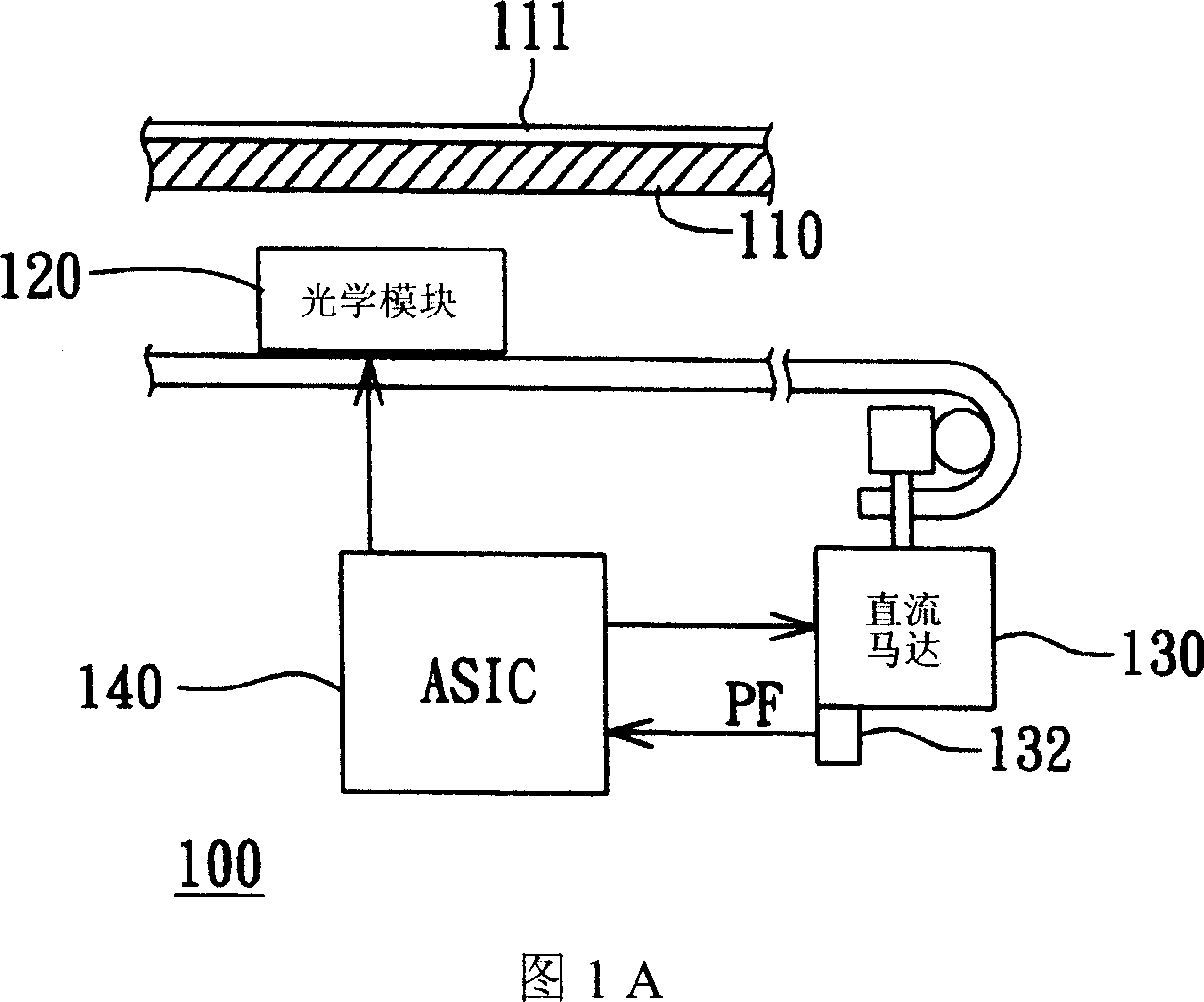
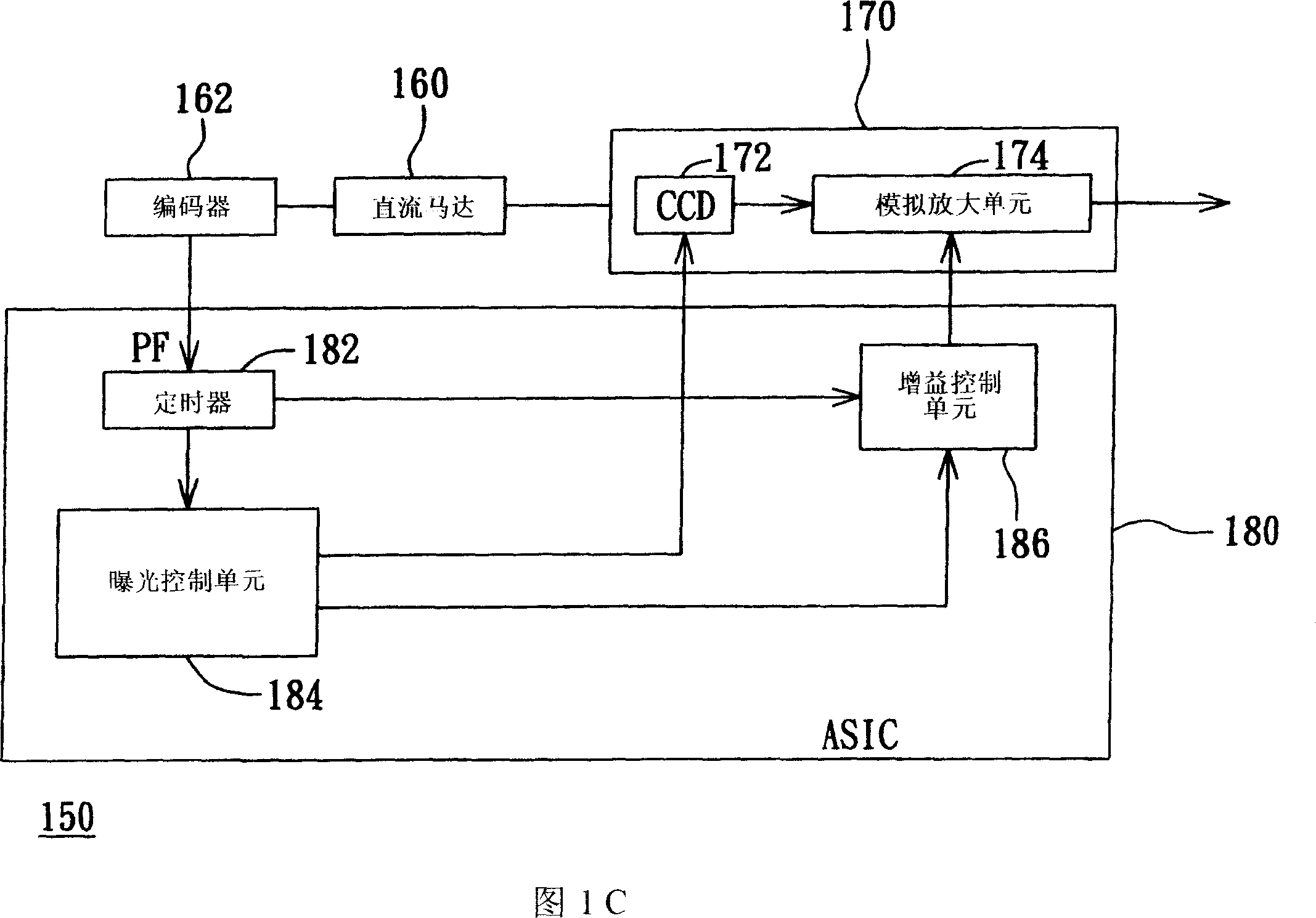
[0007] However, in order to dynamically adjust the AFE gain value of the scanner disclosed in the above-mentioned patent, complex circuits such as gain control unit 186 must be added to the ASIC 180, and the AFE gain compensation is based on the exposure error of the previous scan line to compensate for the next scan line. The exposure of the scanning line, and it is susceptible to external interference during the gain process, so that accurate compensation cannot be made
In addition, the linearity of this kind of analog signal compensation is also poor

Method used


Image

  • Scanner and method thereof
  • Scanner and method thereof
  • Scanner and method thereof

Examples


Embodiment Construction

[0019] The main feature of the present invention is that in a scanner powered by a DC motor, the exposure time of each scanning line is sensed by the optical module, and the image corresponding to each scanning line captured by the light sensing component is digitally captured. The information is digitally amplified to compensate the exposure of each scanning line sensed by the light sensing component, so as to achieve the purpose of consistent image quality.

[0020] Please refer to FIG. 2 , which shows a schematic structural diagram of a scanner according to a preferred embodiment of the present invention. The scanner 200 includes a scanning platform 210 , an optical module 220 , a DC motor 230 and an ASIC 240 . The scanning platform 210 is used to carry a document 211 to be scanned (take a reflective document as an example). The optical module 220 includes a light source 222 , a mirror 224 , a light sensing component 226 and an analog front-end gain unit 228 , wherein the ...


PUM


Abstract

The scanning instrument includes optical assembly, power source, digital gain unit and timer. The optical assembly includes light sensing module for sensing N scanning lines of the file to be scanned, and outputs digital element image data. The power source for driving the optical assembly has position sensor for outputting position feedback signal corresponding the optical assembly. The digital gain unit is for gaining the digital element image data. The timer controls the digital element gaining operation based on the position feedback signal. The scanning method includes: setting K value as 1; driving the optical assembly to sense the K-th scanning line in the file to be scanned and outputting the K-th image data; calculating the K-th exposure time for the K-th scanning line and performing digital gain on the K-th image data; and judging whether K is smaller than N, incrementing 1 to K, if K is smaller than N and backing to the step of driving the optical assembly.

Description

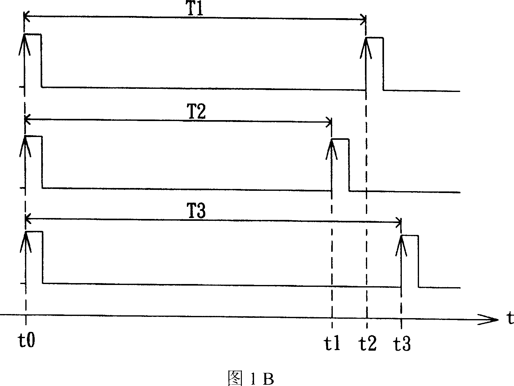
technical field [0001] The present invention relates to a scanner and its scanning method, and in particular to a scanner with a power source capable of feedback control and its scanning method. Background technique [0002] With the advancement of technology, scanners have gradually become an indispensable image capture device for people. The motor is also an important device for driving the photo-sensing components for image capture. Since the DC motor has many advantages such as small size, low noise, low power consumption, and low cost, the scanner based on the DC motor has gradually become a new trend in the scanner market. [0003] Please refer to FIG. 1A , which shows a schematic structural diagram of a known DC motor-based scanner. The scanner 100 includes a scanning platform 110 , an optical module 120 , a DC motor 130 and an Application Specific Integrated Circuit (ASIC) 140 . The DC motor 130 is to drive the optical module 120 to move at...

Claims


Application Information

Patent Timeline
Patent Type & Authority Patents(China)
IPC IPC(8): H04N1/04
Inventor 许明福许四福许弘毅陈星嘉
Owner AVISION PRECISION IND (SUZHOU) CO LTD
Learn More