
Wind energy installation comprising a concentric gearbox/generator arrangement

A technology of gear transmission and planetary gear transmission, which is applied in the direction of gear transmission, transmission, mechanical equipment, etc., can solve the problem of installation weight and cost, and achieve the effect of preventing environmental impact.

Inactive Publication Date: 2007-09-05
AERODYN ENG GMBH
View PDF10 Cites 1 Cited by
  • Summary
  • Abstract
  • Description
  • Claims
  • Application Information

AI Technical Summary

Problems solved by technology

Although this structure allows the components to be interchanged, the overall device is heavier and more expensive

Method used


Image

  • Wind energy installation comprising a concentric gearbox/generator arrangement
  • Wind energy installation comprising a concentric gearbox/generator arrangement
  • Wind energy installation comprising a concentric gearbox/generator arrangement

Examples


Embodiment Construction

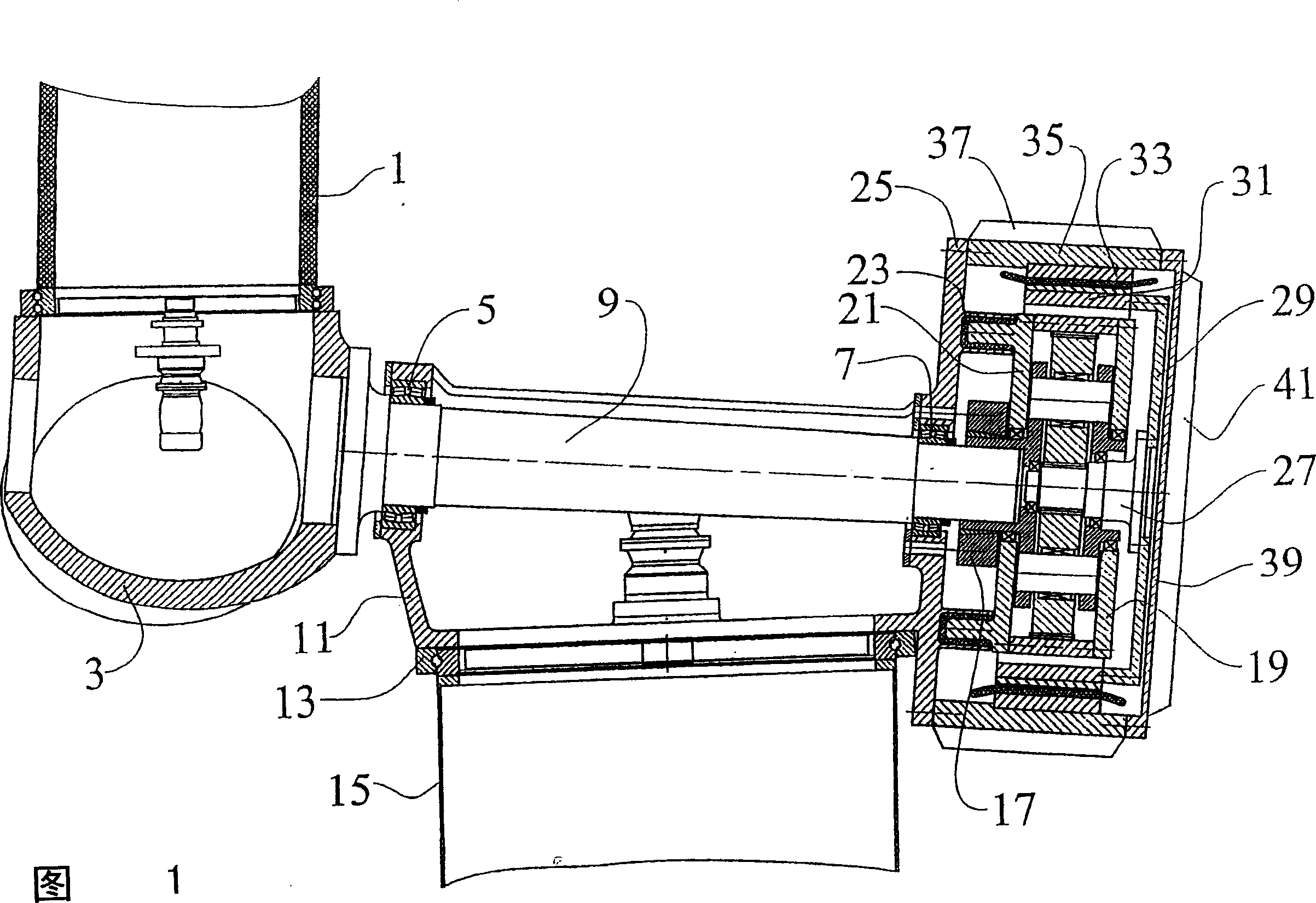
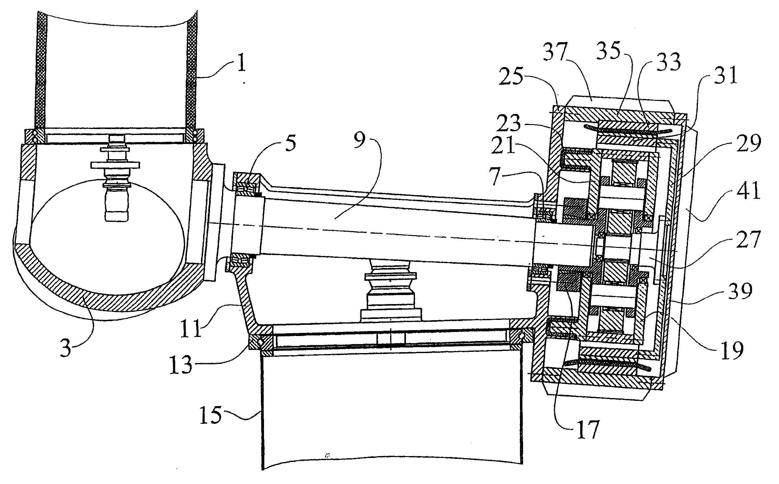
[0022] The blades 1 of the wind turbine rotor, which are only partially shown in FIG. 1, drive a hub 3 which also receives all the additional forces and torques generated by the rotor. A rotor shaft 9 is mounted via a front rotor bearing and a rear rotor bearing 7 , and the rotor load is transmitted to a frame 11 .

[0023] The vertical bearing 13 then transmits the load into the wind power plant tower 15 . Thus, external aerodynamic loads and mass loads of the rotor are introduced into the tower without necessarily passing through the gear transmission or the generator in whole or in part. Via a connection 17 , for example a shrink ring, the gear transmission 19 is connected to the rotor shaft 9 in a torque-resistant manner.

[0024] The gear transmission housing 21 is supported by the elastic member 23 with respect to a base plate 25 . These elastic elements 23 remain absorbing torque fluctuations, structural deformations caused by external loads do not lead to loads on th...


PUM


Abstract

A wind energy plant comprising a rotor, a rotor shaft, a gear, and a generator, the generator embodied as a ring concentrically embracing the gear.

Description

technical field [0001] The invention relates to a wind power plant with a concentric gear drive / generator arrangement. Background technique [0002] A number of drive train arrangements are known for wind power plants. With the exception of gearless machines, most machines consist of a combination of a gear transmission and a generator. In wind power plants, gear drives and generators are traditionally arranged in series as separate components on a frame. In the event of damage, these components can be exchanged individually, but the overall structure is longer and therefore heavier and more expensive. [0003] In EP 811 764 B1 the gear transmission and the generator are housed in a common housing in direct connection, the gear transmission being a single-stage planetary gear transmission, placing the housing directly on the tower. The gear drive and the generator have roughly the same diameter, and the two components are arranged in a direct connection, which results in ...

Claims


Application Information

Patent Timeline
Patent Type & Authority Patents(China)
IPC IPC(8): F03D11/02F03D9/00H02K7/18H02K7/116F16H1/28
CPCF16H1/28F03D9/002Y02E10/725H02K7/116F05B2220/7068H02K7/183F05B2260/2241F16H1/48H02K7/1838F05B2260/40311Y02E10/722Y02E10/72F03D11/02F03D15/00F03D9/25F03D15/10F03D9/00H02K7/18
Inventor S·西格费胜
Owner AERODYN ENG GMBH
Learn More