Cutting edge construction used in perforating device

A technology of punching device and cutting edge, applied in metal processing and other directions, can solve the problems of being stuck, spending a lot of effort, and difficult to remove debris from the penetrated object.

Inactive Publication Date: 2007-09-05
PRIMAX ELECTRONICS LTD
View PDF6 Cites 0 Cited by
  • Summary
  • Abstract
  • Description
  • Claims
  • Application Information

AI Technical Summary

Problems solved by technology

However, when using the above-mentioned traditional blade structure for punching operations, the following problems can occur: the cutting part 11 of the punching tool assembly 10 of the conventional blade structure is a rectangular surface, so when performing the punching operation, The contact area between each punching tool assembly 10 and the penetrated object is the rectangular surface. Due to the large contact area, it takes a lot of effort to cut the same amount and quality of the penetrated object.
However, when using the above-mentioned conventional punching nail structure for punching work, the following problems will occur: In the traditional punching nail structure, when performing the punching work, the two piercing ends 21 first pierce the material and After successively cutting the material, because the heights of the two piercing ends 21 are equal, and because of the pressure applied during the punching process, the debris of the pierced object is easily squeezed and stuck in the "V"-shaped groove 20, The cut penetrating debris is not easy to be removed from the "V" groove 20

Method used


Image

  • Cutting edge construction used in perforating device
  • Cutting edge construction used in perforating device
  • Cutting edge construction used in perforating device

Examples


Embodiment Construction

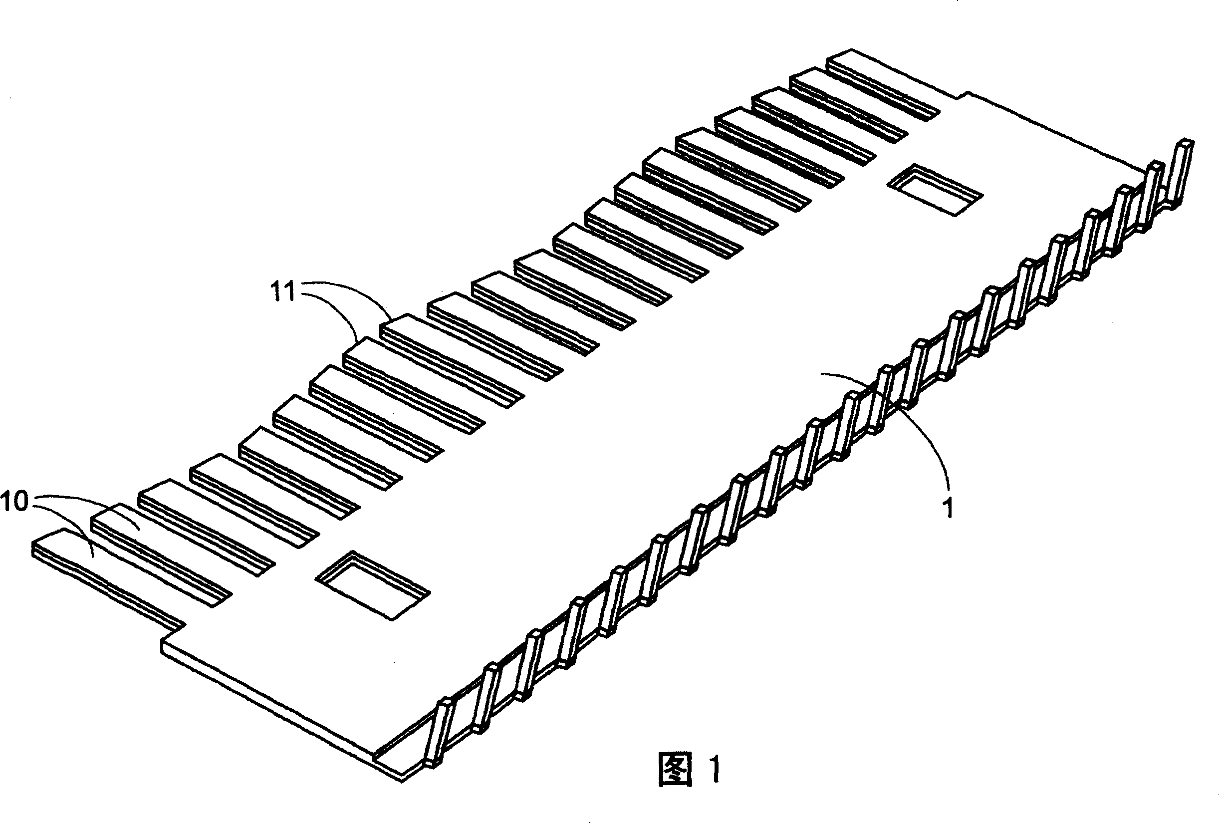
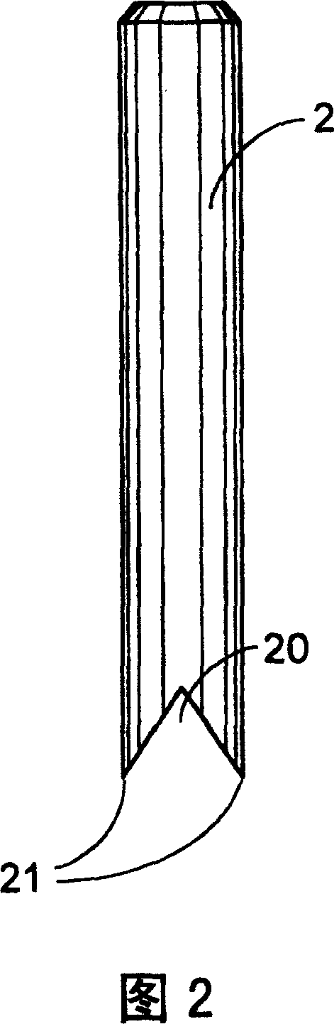
[0028] This embodiment is mainly applied to the blade and the matching knife seat in the punching device, wherein the blade includes several blades for punching, and the blade consists of a main body; a first piercing end; a second a piercing end; and a cutting concave surface. And this knife seat mainly comprises a knife seat main body and several knife seat holes that cooperate with the blade on the blade.

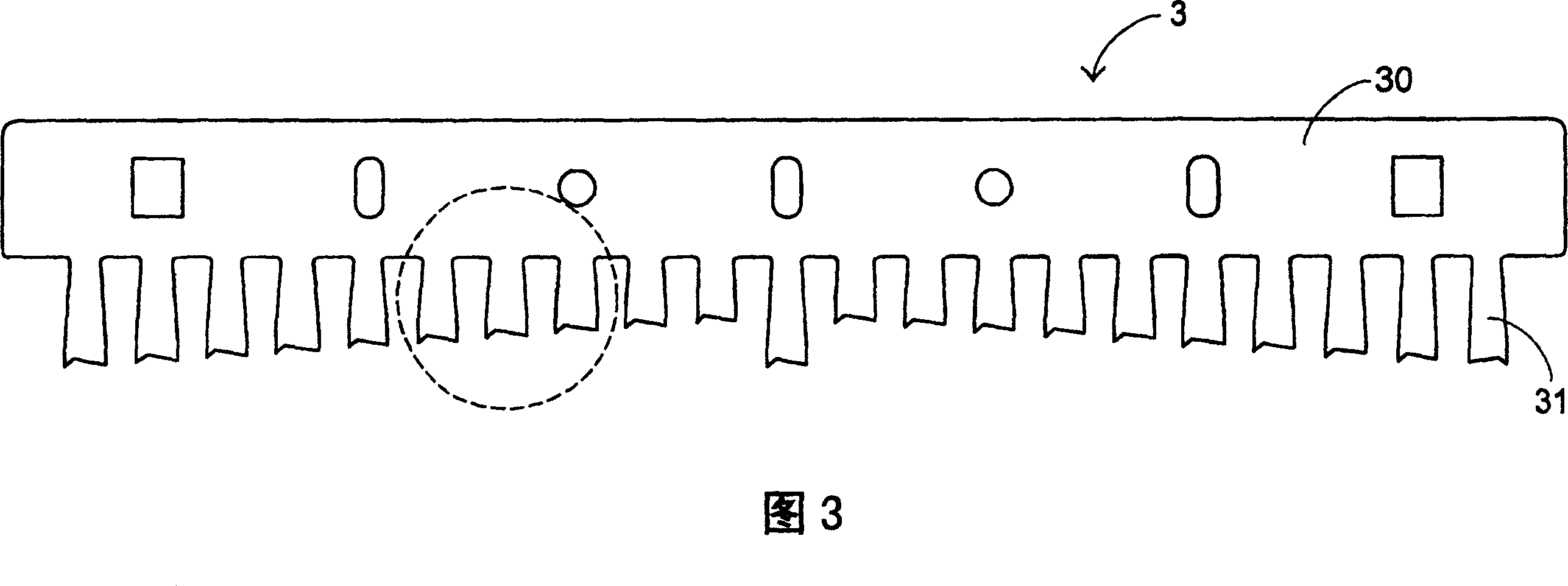
[0029] Please refer to Fig. 3, Fig. 4 and Fig. 5, which are the front schematic diagram of the blade part, the partial enlarged schematic diagram and the three-dimensional schematic diagram of the blade structure of this embodiment, which depict the blade (punching plate) 3 and the knife seat used in the punching device (die plate)5.

[0030] Can further refer to Fig. 3, its blade 3 mainly comprises a blade main body 30 and several blades 31 for punching holes, in the present embodiment, the blade 31 of this blade 3 is arranged in such a way that the length of the blade...


PUM


Abstract

The edge structure for perforator includes one main body; one first piercing end on one side of the bottom end of the main body for piercing some body; one second piercing end on the other side of the bottom end of the main body for piercing some body for further piercing; and one notched cutting surface between the two piercing ends for cutting the pierced body. The cut bits is exhausted via the gap formed between the two piercing ends in different heights.

Description

technical field [0001] The invention relates to a blade structure, in particular to a blade structure applied in a punching device. Background technique [0002] As shown in Figure 1, a blade structure is mainly depicted therein. This traditional structure is the blade structure in the current common punching device. Specifically, the conventional blade structure is mainly composed of a punching body 1 and several punching tool elements 10 . The feature of the blade structure is that several punching tool assemblies 10 are parallel to each other but have different lengths, and the cutting portion 11 of the punching tool assembly 10 is a rectangular surface. When performing a drilling operation, the longest punching tool assembly 10 first cuts the object to be penetrated, and then the punching tool assembly 10 with the second longest length successively cuts. However, when using the above-mentioned traditional blade structure for punching operations, the following problems...

Claims


Application Information

Patent Timeline
Patent Type & Authority Patents(China)
IPC IPC(8): B26F1/00B26F1/44
Inventor 李培源
Owner PRIMAX ELECTRONICS LTD
Why Eureka
Try Eureka