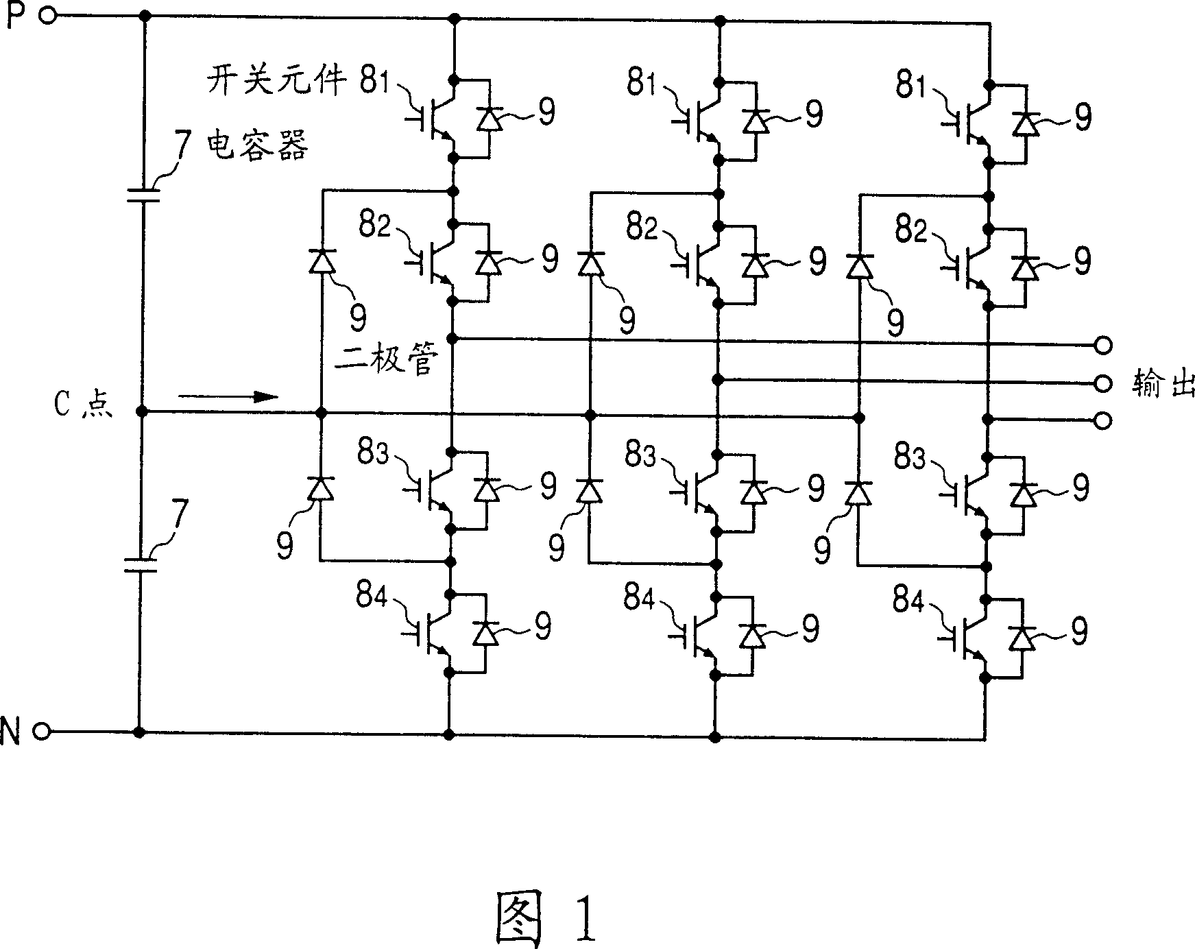
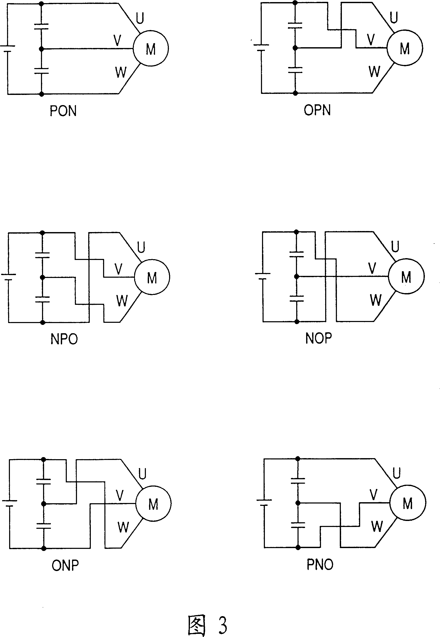
Neutral point clamping PWM inverter
A neutral point clamping and inverter technology, which is applied in the direction of output power conversion device, irreversible DC power input conversion to AC power output, AC power input conversion to DC power output, etc., can solve the problem of neutral point Voltage control devices are expensive, susceptible to noise, etc.
- Summary
- Abstract
- Description
- Claims
- Application Information
AI Technical Summary
Problems solved by technology
Method used
Image
Examples
Embodiment 1
[0039] A three-phase neutral point clamp type PWM inverter device according to Embodiment 1 of the present invention will be described with reference to FIG. 7 . FIG. 7 is a block diagram showing the configuration of a PWM pulse calculator applied to the three-phase neutral point clamp type PWM inverter device of this embodiment. As shown in Figure 7, the three-phase neutral point clamped PWM inverter device of this embodiment has a parameter calculator 101 for neutral point potential control, a vector time calculator 102, a vector time register 103, and a PWM mode setting device 104.
[0040] In the case where the three-phase neutral point clamp type PWM inverter device of the present embodiment outputs the output voltage vector V, according to the vectors constituting the region (regions 1 to 6) where the output voltage vector V exists shown in FIG. 4 , Output PWM pulse. Assuming that the classification of the vectors constituting the region is as shown in FIG. 4, the vect...
Embodiment 2
[0113] The second neutral point voltage control device of the present invention will be described. FIG. 8 is a block diagram showing the structure of the neutral point voltage control device of this embodiment. As shown in FIG. 8 , the neutral point voltage control device of this embodiment is composed of a subtractor 1 , two comparators 2 , a calculation circuit 3 and an isolation circuit 10 .
[0114] Subtractor 1 output from the neutral point voltage V CN subtract the first reference voltage V ref1 value. The first reference voltage value V ref1 is a half voltage value (1 / 2·V PN ).
[0115] In addition to the first reference voltage value V ref1 In addition, a second reference voltage value V ref2 and the third reference voltage V ref3 . The second reference voltage value V ref2 and the third reference electric value V ref3 As shown in Figure 9, they are negative and positive values, respectively.
[0116] A comparator 2 where the output value of the subtractor ...
Embodiment 3
[0123] Next, a neutral point voltage control device according to Embodiment 3 of the present invention will be described with reference to FIG. 10 . Fig. 10 is a block diagram showing the configuration of a neutral point voltage control device according to Embodiment 3 of the present invention. As shown in FIG. 10, the difference between the neutral point voltage control device of this embodiment and the neutral point voltage control device of the above-mentioned embodiment is that a comparator 4 is provided instead of two comparators 2, and a storage device 5 is provided instead of two comparators 2. Calculation circuit 3.
[0124] Comparator 4 input from the neutral point voltage V CN subtract the first reference voltage V ref1 value, the output value of the subtractor 1 is more than the second reference voltage value V ref2 Small case, in the second reference voltage value V ref2 Above the third reference voltage value V ref3In the following cases, the ratio of the thi...
PUM
 Abstract
Description
Claims
Application Information
 - R&D
- Intellectual Property
- Life Sciences
- Materials
- Tech Scout
- Unparalleled Data Quality
- Higher Quality Content
- 60% Fewer Hallucinations
Browse by: Latest US Patents, China's latest patents, Technical Efficacy Thesaurus, Application Domain, Technology Topic, Popular Technical Reports.
© 2025 PatSnap. All rights reserved.Legal|Privacy policy|Modern Slavery Act Transparency Statement|Sitemap|About US| Contact US: help@patsnap.com


