
System and method for analyzing modeling accuracy while performing reverse engineering with 3D scan data

a technology of reverse engineering and modeling accuracy, applied in the field of cad (computer aided design), can solve problems such as inaccurate data, and achieve the effect of updating the accuracy loss information availabl

Active Publication Date: 2021-03-30
3D SYST INC
View PDF42 Cites 0 Cited by
  • Summary
  • Abstract
  • Description
  • Claims
  • Application Information

AI Technical Summary

Benefits of technology

The system effectively tracks and manages accuracy loss throughout the reverse engineering process, enabling users to maintain data integrity by providing continuous updates on accuracy deviations and allowing for parameter adjustments to stay within specified tolerances, thus ensuring the quality of the reverse-engineered CAD model.

Problems solved by technology

The error display graphically notifies the user of undesirable editing or modeling parameters.

Method used


Image

  • System and method for analyzing modeling accuracy while performing reverse engineering with 3D scan data
  • System and method for analyzing modeling accuracy while performing reverse engineering with 3D scan data
  • System and method for analyzing modeling accuracy while performing reverse engineering with 3D scan data

Examples


Embodiment Construction

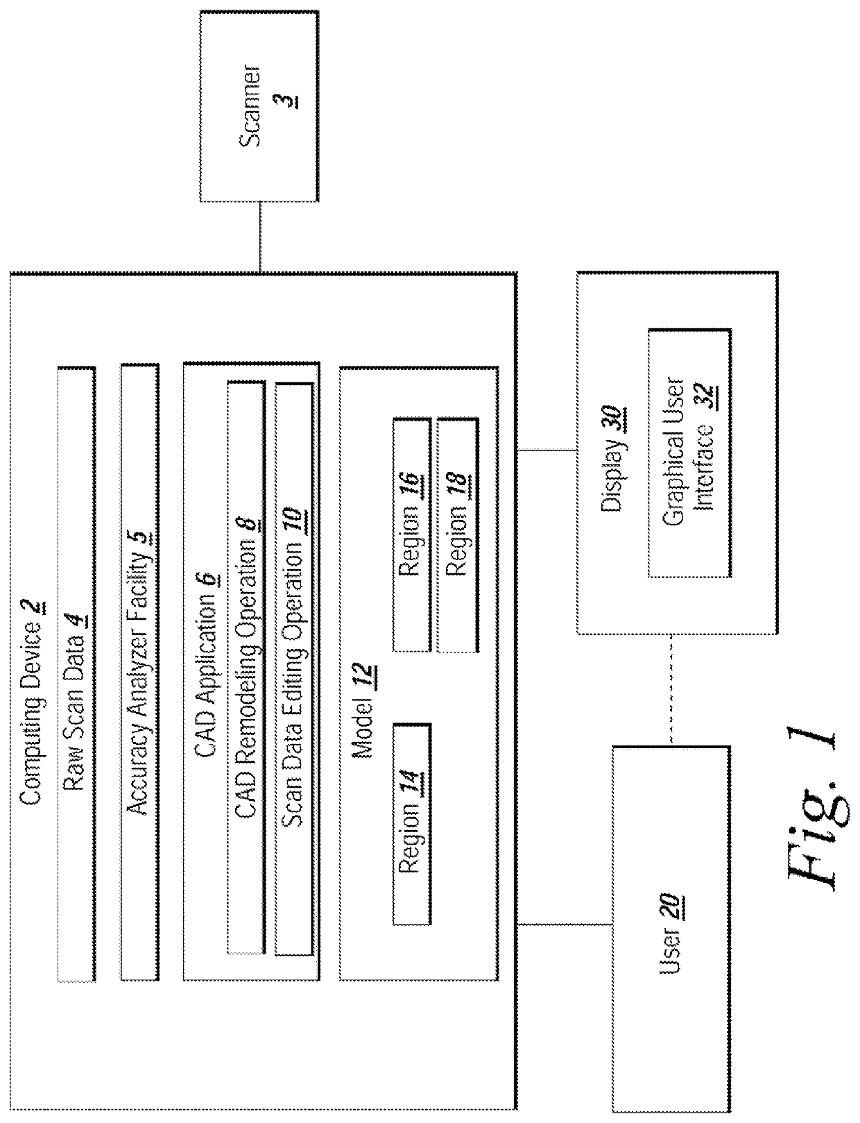
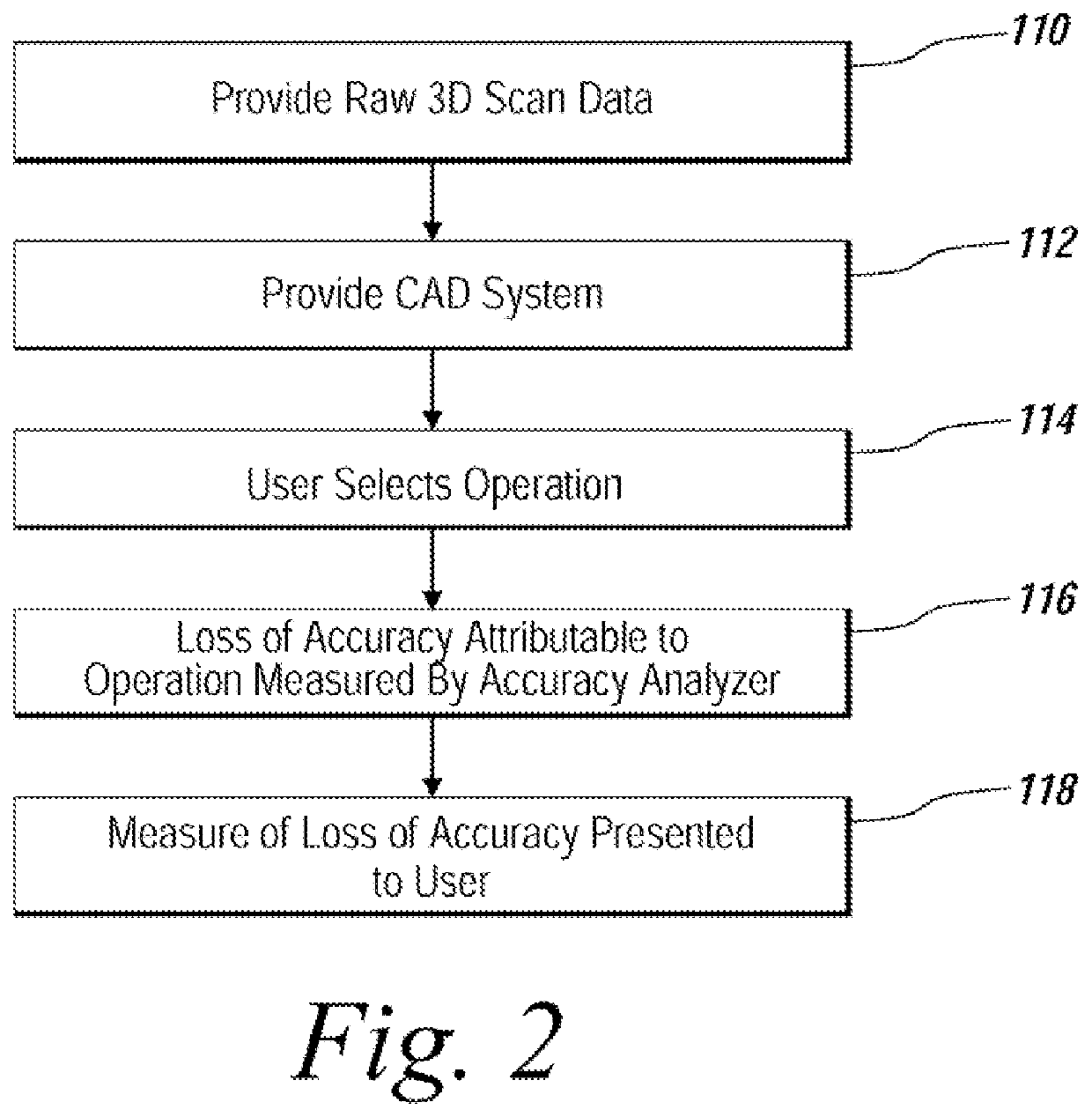
[0028]The embodiments of the present invention provides accuracy loss information to a user performing reverse engineering using 3D scan data. The accuracy loss information indicates the effect of scan data editing operations or CAD remodeling operations on 3D scan data. Accuracy loss indicates the distance deviation between a chosen reference 3D scan data (e.g.: the original scan data or the previous state of the 3D scan data prior to modification) and the modified raw 3D scan data or a derivative of the 3D scan data such as a surface or solid body. Changes to the reference scanned data that have been or will be caused by a scan data editing or CAD remodeling operation are noted for a user. In one implementation, the effect of a proposed operation is presented to the user in a preview pane before the operation is completed.

[0029]FIG. 1 depicts an environment suitable for practicing an embodiment of the present invention. A computing device 2 includes a collection of raw 3D scan dat...


PUM


Abstract

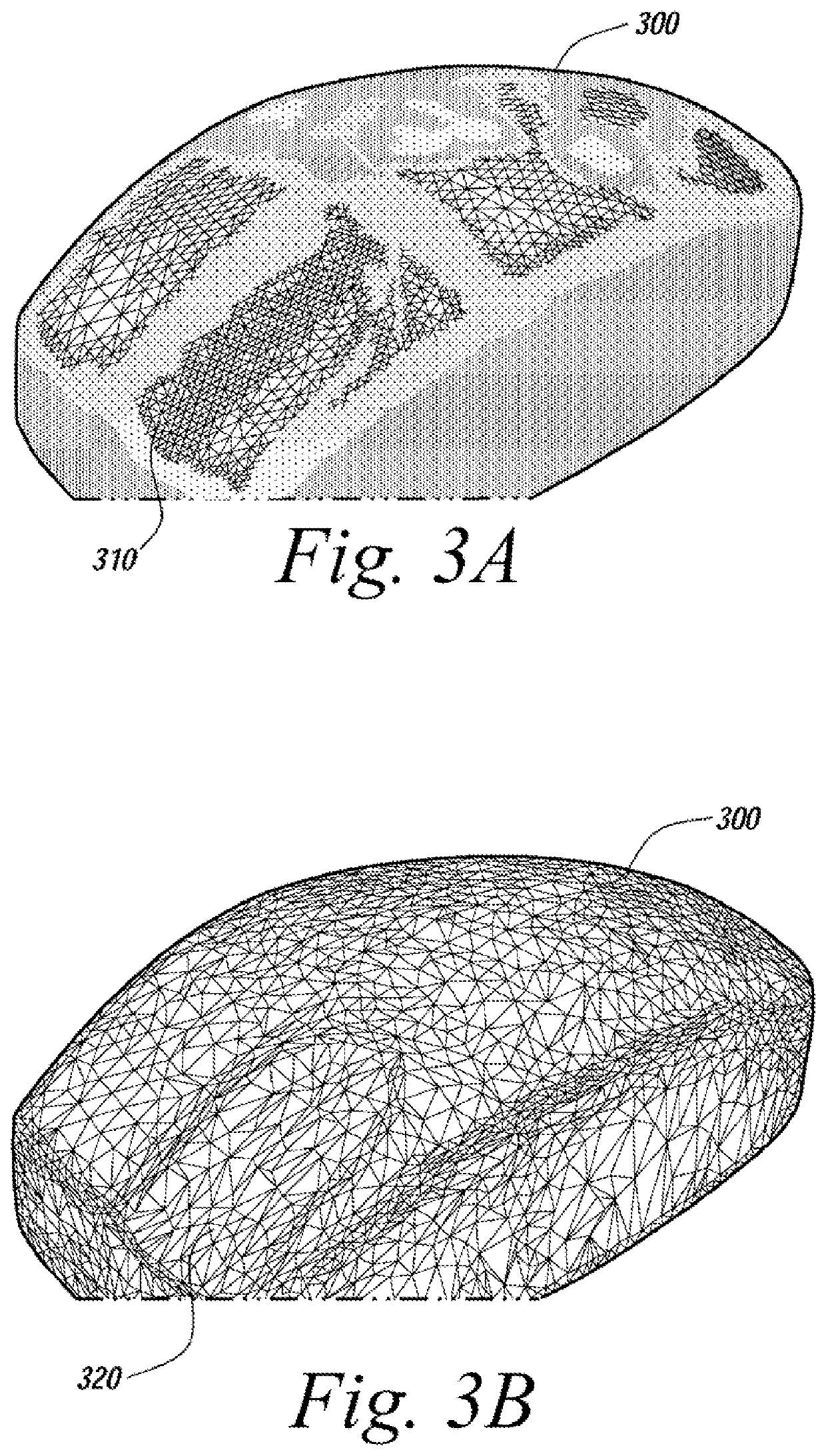
An automated mechanism for measuring the amount of accuracy loss attributable to reverse engineering processes that use 3D scan data is discussed. The embodiments provide a mechanism that displays to a user the effect scan data editing and CAD remodeling operations have on scan data accuracy. Additionally, the user can choose the way the graphical display illustrates the error distribution on the model such as by color mapping and whisker mapping. The accuracy loss may be displayed to the user after finishing an editing / modeling command or during the previewing of the command thereby allowing a user to take appropriate action. Parameters may also be adjusted programmatically based on the amount of accuracy loss determined to be attributable to scan data editing or CAD remodeling operations.

Description

RELATED APPLICATION[0001]This is a reissue application of U.S. Pat. No. 7,821,513, filed Apr. 9, 2007, issued Oct. 26, 2010, and which claims the benefit of a U.S. Provisional Application entitled, “System and Method for Analyzing Modeling Accuracy While Performing Reverse Engineering With 3D scan data”, Application No. 60 / 767,517, filed May 9, 2006.FIELD OF THE INVENTION[0002]The embodiments of the present invention relate generally to CAD (Computer Aided Design) and more particularly to the measurement of accuracy loss during reverse engineering processes.BACKGROUND[0003]Computer Aided Design (CAD) applications are used to produce computer models of two and three dimensional objects as part of the production process for the actual physical device being modeled. The models frequently include multiple CAD part bodies which must be individually designed. A CAD part body is a computational model used by a CAD application to hold a solid or a sheet (open body with zero thickness) geome...

Claims


Application Information

Patent Timeline
Patent Type & Authority Patents(United States)
IPC IPC(8): G06T15/00G06T17/20G06F30/00G06F17/50
CPCG06T17/20G06F30/00G06T17/205
Inventor BAE, SEOCKHOONLEE, DONGHOON
Owner 3D SYST INC
Learn More