Signaling techniques for DC track powered model railroads

a technology of dc track and model railroad, applied in the direction of motor/generator/converter stopper, dynamo-electric converter control, ac motor stopper, etc., can solve the problem of limited number of different remote control effects, and achieve the effect of simplifying remote control operations and expanding remote control operations

Inactive Publication Date: 2011-04-12
SEVERSON FREDERICK E +1
View PDF31 Cites 8 Cited by
  • Summary
  • Abstract
  • Description
  • Claims
  • Application Information

AI Technical Summary

Benefits of technology

[0033]The direction control switch, 304, in FIG. 3, which normally is only used to change the direction of the engine by changing the polarity of DC voltage on the track, can be used to do simple remote control operations under certain conditions. This new remote control signal will be called, PR, for Polarity Reversal. The on-board motor controller, 402, supplies a specific polarity of voltage to the motors independent of the polarity of the track voltage on rails 307 and 308. That is, the motor controller, 402, can prevent the engine from changing direction when the direction switch, 304, is toggled between position A and B, 305 and 306. Instead, the on-board state generator will specify the motor direction to the motor controller, 402. Direction changes will be made by changing the OBSG state using other remote control signals or even combinations of signals that may involve PR signals and possibly by the state of on-board state generator, 405.
[0034]Having this one single remote control signal, PR, plus an on-board state generator and a motor controller that can be programmed to interpret this signal can improve the operation of DC-powered trains in a number of ways. For instance, when power is applied to the engine, toggling the direction switch, 304, on the track power-pack could actuate a remote control feature like blowing the horn but will not cause the engine's direction to change. However, changing direction of an engine could be done in the normal way with a minor limitation: if the engine is stopped by turning the power off and the direction control switch, 304, is toggled, reapplying the power could cause the direction of the engine to change. In this way, the direction switch, 304, would still provide the familiar operation control that is standard for DC powered trains. This is a very natural use of the direction switch since the DC train operator is not in the habit of using the direction switch to change direction while an engine is moving; otherwise it causes an abrupt reversal of his locomotive which is very unrealistic and may damage the engine or, at least, cause a train derailment. Hence, changing track polarity while the engine is moving is a new operation that can be used for remote control functions without violating the normal operating standard.
[0035]Other features like turning on and off the bell can be done by using a coded signal such as changing DC track polarity for two long and one short period of time or perhaps a short duration of changing DC track polarity will turn on or off the bell while a long duration of changing DC track power will blow the whistle. Or the bell can be turned on or off if a polarity reversal is used while the track voltage is low but a PR will turn on the horn if the track voltage is high.
[0041]This method of making a selection with one remote signal and operating it with another is very simple for either AC or DC power model engines in neutral. If reset is a non-moving state, using this technique is ideal for initializing the operation of an engine such as starting the engine sounds, turning on various lights, etc. For instance, imagine that we moved the throttle up and down a total of six times (6 HVP's) after entering reset which changes the OBSG to a state called “engine sound volume”. Then, the second remote control signal could be used to change the volume from the present value to progressively lower values until it returned to the highest value in a continuous loop. Moving the throttle up and down again at any of the volume setting would lock-in the volume choice and move to the next state of the OBSG for another option. For instance, this next option could be “overhead blinking light”. Now, toggling the second remote control signal could be used to toggle the light between on and off. This approach of selecting and operating different options could proceed indefinitely. Again, the use of the OBSG increases the number of remote control options.
[0042]It is, in fact, possible to nest sets of options so the 
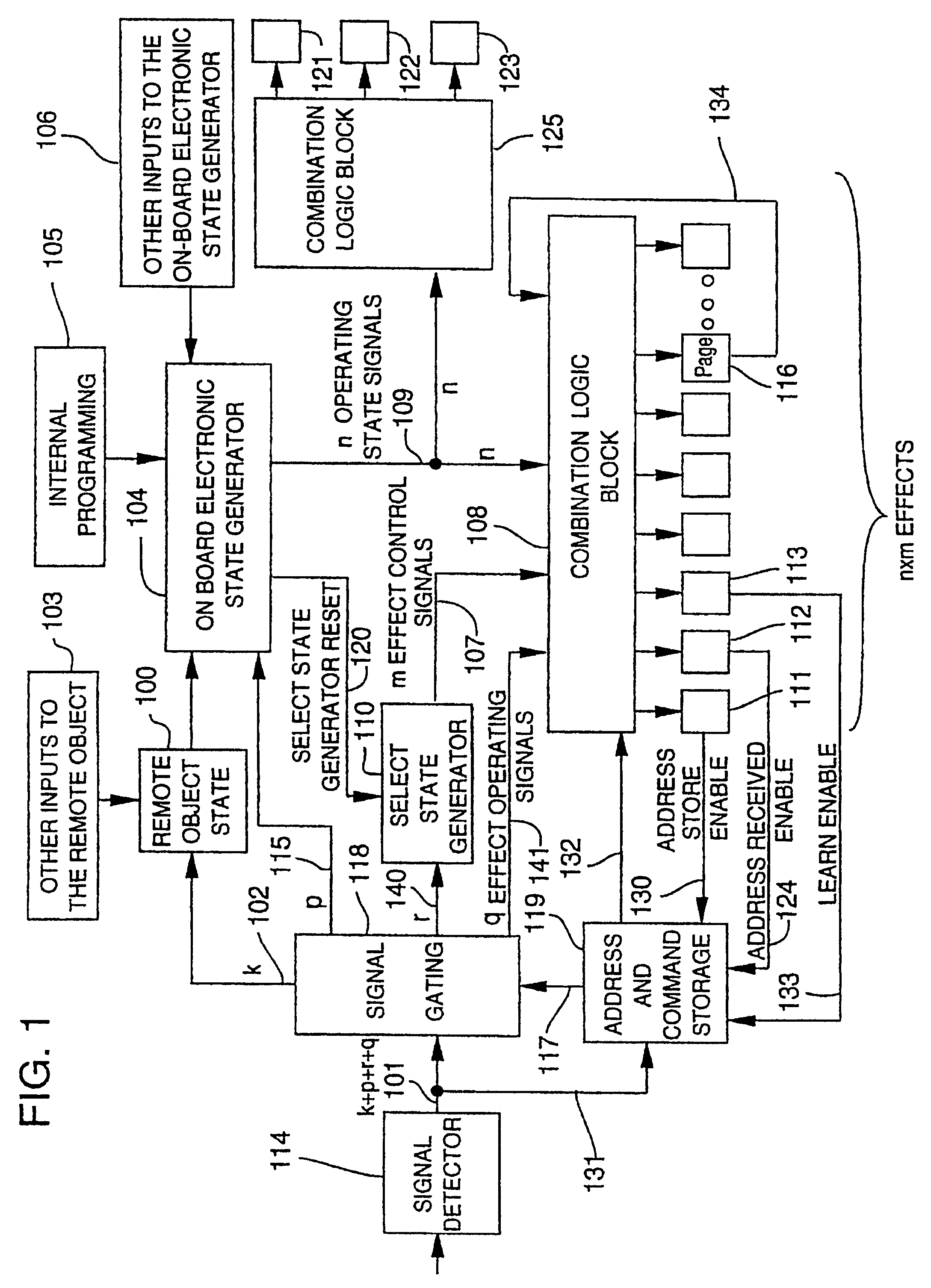
list of options does not become too unwieldy. For example, the in Reset option 12, operating the option could perform “page advance”. The next option available to the operator might then be Page 2 / Reset option 1. Now, repeated uses of HVP would advance through Page 2 options. Option 13 on every page (higher than page 1) could be “return to page 1 options”. Nesting like this can produce any number of pages with any number of options per page in a way that is easy for the operator to use.Other Remote Control Signals for Engines, Cars and Accessories on DC Powered Layouts
[0046]This invention describes new remote control signals that can be easily generated within the existing DC powered model train standard and how these signals can be used with an on-board state generator in the remote object (usually an engine) to expand remote control operations. In particular, when two remote control signals are available, the idea of “select” and “operate” can be used to simplify remote control operations.

Problems solved by technology

In this way, the number of different remote control effects is only limited by the number of available states for the On-Board State Generator.

Method used


Image

  • Signaling techniques for DC track powered model railroads
  • Signaling techniques for DC track powered model railroads
  • Signaling techniques for DC track powered model railroads

Examples


Embodiment Construction

Methods to generate a polarity reversal (PR) remote control signals for DC powered layouts

[0065]There are two types of simple remote control operations that will respond to a PR. The first is a sustained response like a horn where the effect is on as long as the remote control signal is applied. The second is a toggle or counting action where the response is to switch to an alternative each time the remote control signal is applied. It seems convenient to use the direction switch on the power pack, such as the switch, 304 in FIG. 3, to provide a PR to blow the horn as long as the PR is present and then turn the horn off as soon as the direction switch is returned to its original position. However, when used to toggle a remote feature on and off in the engine, there are two acceptable possibilities. We could affect the toggle when a single PR is received such as when the switch, 304, is changed or we could only toggle the remote effect when two PR are received such as when the direct...


PUM


Abstract

Electronic circuits and methods are provided for remote control of a locomotive in a model railroad layout having an interruptible DC power supply coupled to the railroad track. The locomotive motor is isolated from the track so as to allow use of polarity reversals on the track power signal for controlling remote effects in the locomotive such as sound effects. An on-board electronic state generator is provided in the locomotive for maintaining one at a time of a predetermined set of states, at least one of the states having a corresponding remote effect associated therewith. Remote control signals such as a reverse in polarity of the DC track power signal are used to clock the state generator to a desired state, thereby permitting control of a plurality of remote effects using only the traditional DC power supply interface. The locomotive motor is controlled by a motor reverse unit so that the motor direction is controllable independently of the polarity of the DC power signal applied to the track. Accordingly, both motor direction and remote effects are controllable using only the throttle and polarity reversal switch which are available in known DC model railroad power supplies.

Description

[0001]This application is a continuation-in-part of U.S. Ser. No. 08 / 012,364, filed Feb. 1, 1993 now U.S. Pat. No. 5,394,068, which is a division of U.S. Ser. No. 07 / 480,078, filed Feb. 14, 1990, now U.S. Pat. No. 5,184,048, which is a division of U.S. Ser. No. 07 / 037,721, filed Apr. 13, 1987, now U.S. Pat. No. 4,914,431 which is a division of Ser. No. 06 / 672,397, filed Nov. 16, 1984, now abandoned. ©Copyright Frederick Severson and Patrick Quinn 1993: The disclosure of this patent document contains material which is subject to copyright protection. The copyright owners have no objection to facsimile reproduction by anyone of the patent document or the patent disclosure, as it appears in the Patent and Trademark Office patent file or records, but otherwise reserve all copyrights whatsoever.FIELD OF THE INVENTION[0002]This invention describes ways to extend the controls and features of the model railroad train control and sound system described in U.S. Pat. No. 4,914,431. In particul...

Claims


Application Information

Patent Timeline
IPC IPC(8): H02P7/00A63H19/24H02J13/00
CPCA63H19/10A63H19/14A63H19/24A63H2019/246Y10S104/01H02J13/0001H02J13/00009
Inventor SEVERSON, FREDERICK E.QUINN, PATRICK ALLEN
Owner SEVERSON FREDERICK E
Why Eureka
Try Eureka