
Needle tip cover

Inactive Publication Date: 2006-02-28
BECTON DICKINSON & CO
View PDF72 Cites 128 Cited by
  • Summary
  • Abstract
  • Description
  • Claims
  • Application Information

AI Technical Summary

Benefits of technology

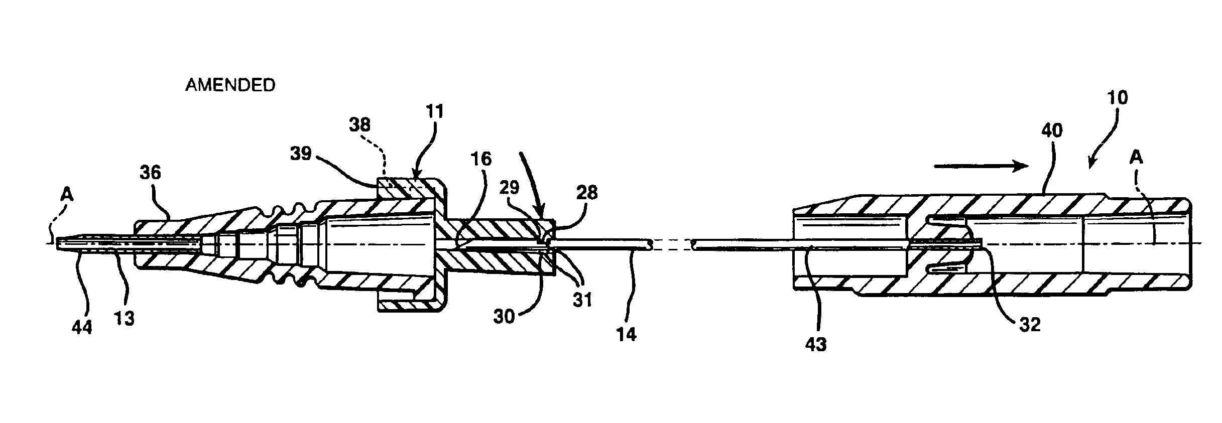
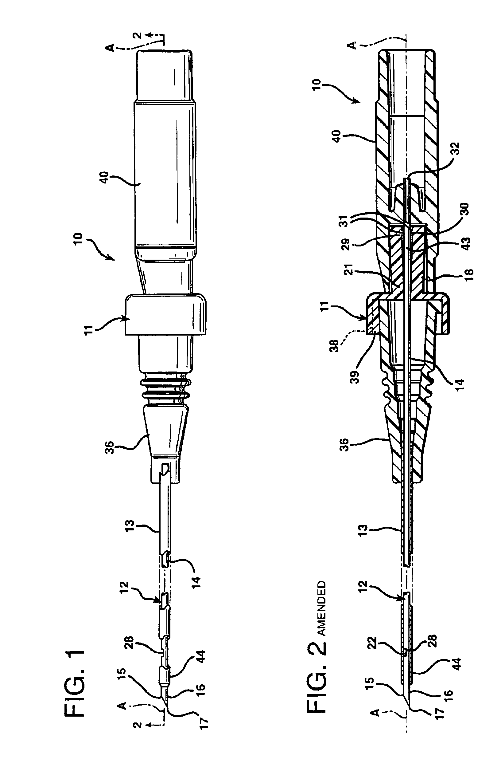
[0011]The cover may have a bearing for circumscribing and guiding during coaxial sliding on the elongate shank. The part which extends hangs cantilever off the bearing to extend beyond the sharpened point preventing accidental injury. The lock may have a change in contour of the needle near where the elongate shank joins the tip so when the cover interengages with the change in contour it becomes locked relative to the needle preventing further axial movement.
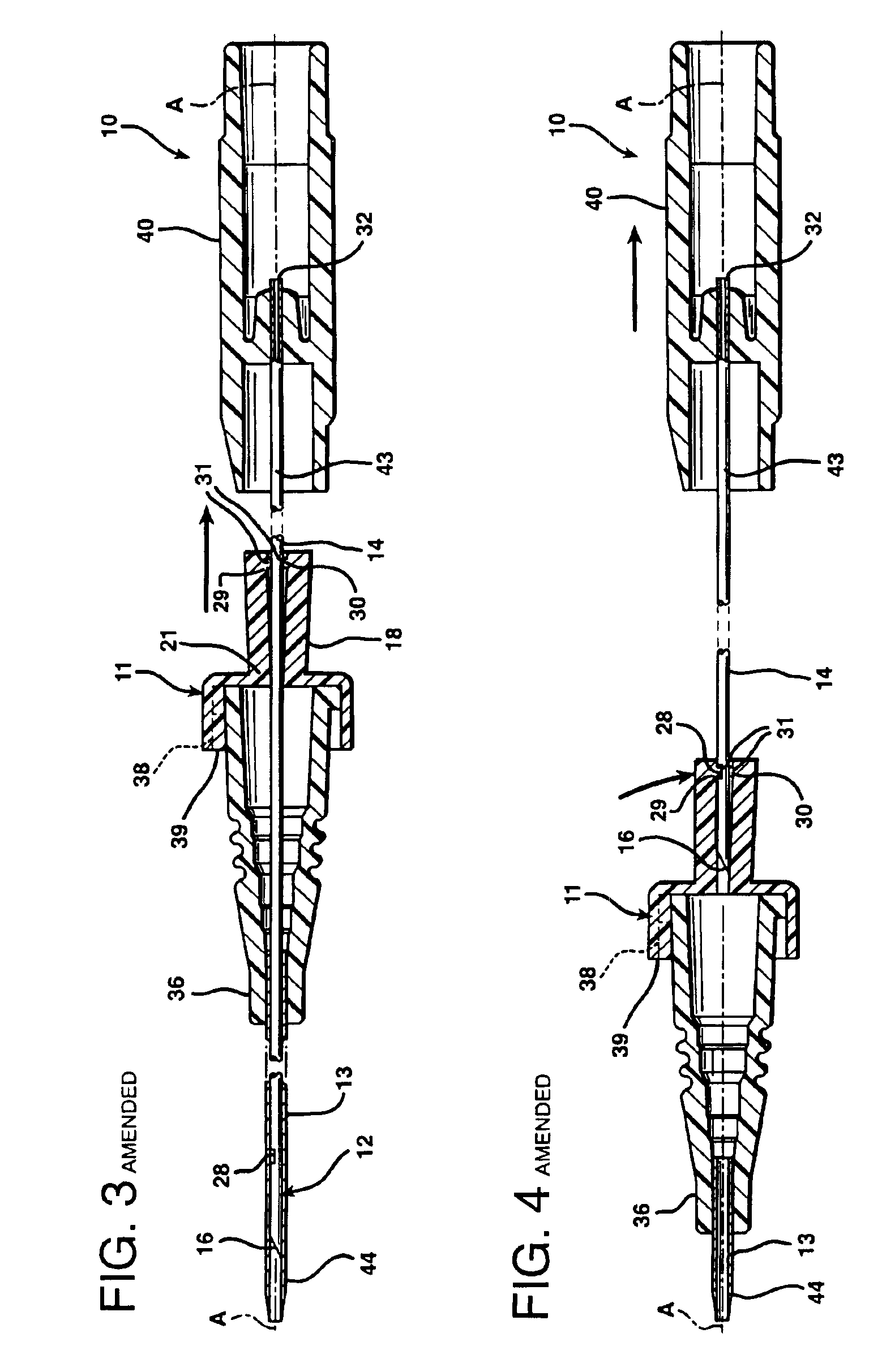
[0012]The bearing has an inside diameter which most preferably rides upon the shank for axial movement therealong and the bearing is such that engagement with the change in contour prevents distal travel. The part which extends controls the proximal axial movement of the cover up the elongate shank away from the tip after thus locking the cover near the tip.
[0014]The invention may be a part of a catheter assembly having a catheter and an adapter connected to one another for fluid communication and carried coaxially about a needle and hub. The catheter has a bore therethrough sized to surround the elongate shank of the needle for movement therewith during insertion and therealong during placement. A retaining means on the adapter and on the cover may releasably attach the cover to the adapter while the catheter and adapter are on the elongate shank of the needle. The retaining means permit the needle and cover to be disengaged from the catheter and adapter after placement of the catheter in the vessel. The lock cooperates and secures the cover to prevent the cover from axial movement relative to the needle tip after the cover is positioned near the tip.

Problems solved by technology

All of them are cumbersome, expensive and interfere with the normal and accepted procedure for the insertion of an over the needle catheter.
Those needle guards are cumbersome and interfere with the single hand over the needle catheter placement procedure as disclosed in Stanley, U.S. Pat. No. 3,714,945.

Method used


Image

  • Needle tip cover
  • Needle tip cover
  • Needle tip cover

Examples


Embodiment Construction

[0033]While this invention is satisfied by embodiments in many different forms, there is shown in the drawings and will herein be described in detail, a preferred embodiment and alternate embodiments of the invention, with the understanding that the present disclosure is to be considered as exemplary of the principles of the invention and is not intended to limit the invention to any one of the embodiments illustrated. The scope of the invention will be measured by the appended claims and their equivalents.

[0034]FIGS. 1 and 5 are side views of a catheter assembly 10 with a needle tip cover 11 wherein a needle 12 is fully seated within a catheter 13 of the catheter assembly 10. The needle 12 has an elongate shank 14 relative to an axis “A” thereof. The needle 12, preferably made of metal such as medical grade stainless steel, has a tip 15 at its distal axial end 16 terminating with a sharpened point 17. A cover 11 is coaxially associated with the elongate shank 14 for sliding movemen...


PUM


Abstract

A needle and a cover with a needle having an elongate shank and a tip with a sharpened point. The cover is coaxially associated with the elongate shank for movement therealong toward the tip and includes a part for extending beyond the sharpened point when the cover is positioned near the tip. A lock associated with the needle and cover cooperates with and holds the cover to prevent axial movement relative to the needle tip after positioning the cover near the tip. A retaining member on the adapter and on the cover releasably attach the cover to the adapter while on the elongate shank of the needle allowing the needle and cover to be disengaged from the catheter and adapter after placement.

Description

[0001]This application is a division of patent application Ser. No. 08 / 364,071 filed Dec. 27, 1994, now U.S. Pat. No. 5,558,691, which is a continuation of patent application Ser. No. 08 / 114,988 filed Aug. 12, 1993, now abandoned, which is a continuation of patent application Ser. No. 07 / 512,284 filed Apr. 20, 1990, now abandoned.FIELD OF THE INVENTION[0002]This invention relates to a needle tip cover to prevent transmission of infection and more particularly, relates to a tip cover for locking about the tip of a disposable needle after use to prevent accidental delivery of infectious organisms by penetration of the used needle tip into an animal.BACKGROUND OF THE INVENTION[0003]With concern about infection, transmission of AIDS, hepatitis and similar incurable diseases of the blood, methods and devices to enclose the used disposable needle tip have become very important and in great demand. Many approaches to guard the needle, protect users and / or otherwise prevent injury have been...

Claims


Application Information

Patent Timeline
IPC IPC(8): A61M5/00A61M25/06
CPCA61M5/3273A61M25/0618A61M2005/325
Inventor CRAWFORD, MARK A.ERSKINE, TIMOTHY J.PETERSON, GERALD H.
Owner BECTON DICKINSON & CO
Learn More