
Integrated disposable ear piercing earring and clutch cartridge and ear piercing instrument for use therewith

a technology for ear piercing instruments and cartridges, which is applied in the field of disposable ear piercing earring and clutch cartridges and instruments for use there, can solve the problems of increasing the chance of cross contamination between successive ear piercing patients and the ear piercing instrument operator, affecting the accuracy of ear piercing, and reducing the amount of handling of ear piercing earring and clutch

Inactive Publication Date: 2002-12-10
INVERNESS CORPROATION
View PDF8 Cites 5 Cited by
  • Summary
  • Abstract
  • Description
  • Claims
  • Application Information

AI Technical Summary

Benefits of technology

A further object of the invention is to provide an ear piercing earring cartridge which increases ear piercing aiming accuracy.
Yet another object of the invention is to provide an improved ear piercing earring cartridge utilizing a sliding bullet, the bullet being formed in a clam shell construction hinged at the rear of the bullet sliding direction to allow for smooth ejection of the ear piercing earring.
Still another object of the present invention is to provide an improved ear piercing instrument which reduces the amount of handling of the ear piercing earring and clutch.

Problems solved by technology

In all cases excessive handling with a high potential for earrings coming in contact with the fingers of the ear piercing instrument operator result, increasing the chance of cross contamination between successive ear piercing patients and the ear piercing instrument operator.
Furthermore, these systems do not protect the instrument itself from contamination due to human contact or back splashing of blood or fluids during piercing.
The earring clasps or clutches are housed in a separate cartridge and are not totally encapsulated, but make direct contact with the operator difficult.
However, they suffer from the disadvantage that the disposable cartridges which prevent contact between each person and the instrument do not fully cover the piercing area of the instrument itself which is proximate to the earlobe allowing potential for contamination from blood back splash or the like.
Additionally, because the cartridge must be inverted or slid by hand by the ear piercing instrument operator, the cartridges are still excessively handled exposing the cartridges to contamination from the operator as well as the susceptibility of being dropped.
This is particularly significant when handling the clutch cartridge in which the clutches are exposed to some extent and may even be touched during handling.
A further deficiency, particularly in the ear piercing cartridge assembly of U.S. Pat. No. 5,007,918 is the use of a pair of bullet shaped capsules which are split longitudinally with the halves being connected by means of a thin hinge molded into the halves at the front of the bullet in the ejection direction.
Additional force is required to break the hinge thus making the procedure balky, preventing smooth insertion of the ear piercing earring.
Such force requirements make operation difficult for some operators.
A further deficiency in the prior art ear piercing cartridge assemblies is that during the ear piercing process, it is necessary for the operator to hold the earlobe firmly in place against the clutch cartridge.
If the operator does not follow rigid cleansing procedures, the potential for contamination of the earlobe being pierced exists.
Additionally, because the earlobe is not firmly retained in place, even when held by the operator's fingers, it is possible that nervous ear piercing patients will move their head causing the earring being inserted to be deflected from its intended path causing it to pierce portions of the ear other than the intended location, or it could be deflected sideways and only partially into the earlobe causing pain, bleeding and the need to reinsert the earring.

Method used


Image

  • Integrated disposable ear piercing earring and clutch cartridge and ear piercing instrument for use therewith
  • Integrated disposable ear piercing earring and clutch cartridge and ear piercing instrument for use therewith
  • Integrated disposable ear piercing earring and clutch cartridge and ear piercing instrument for use therewith

Examples


Embodiment Construction

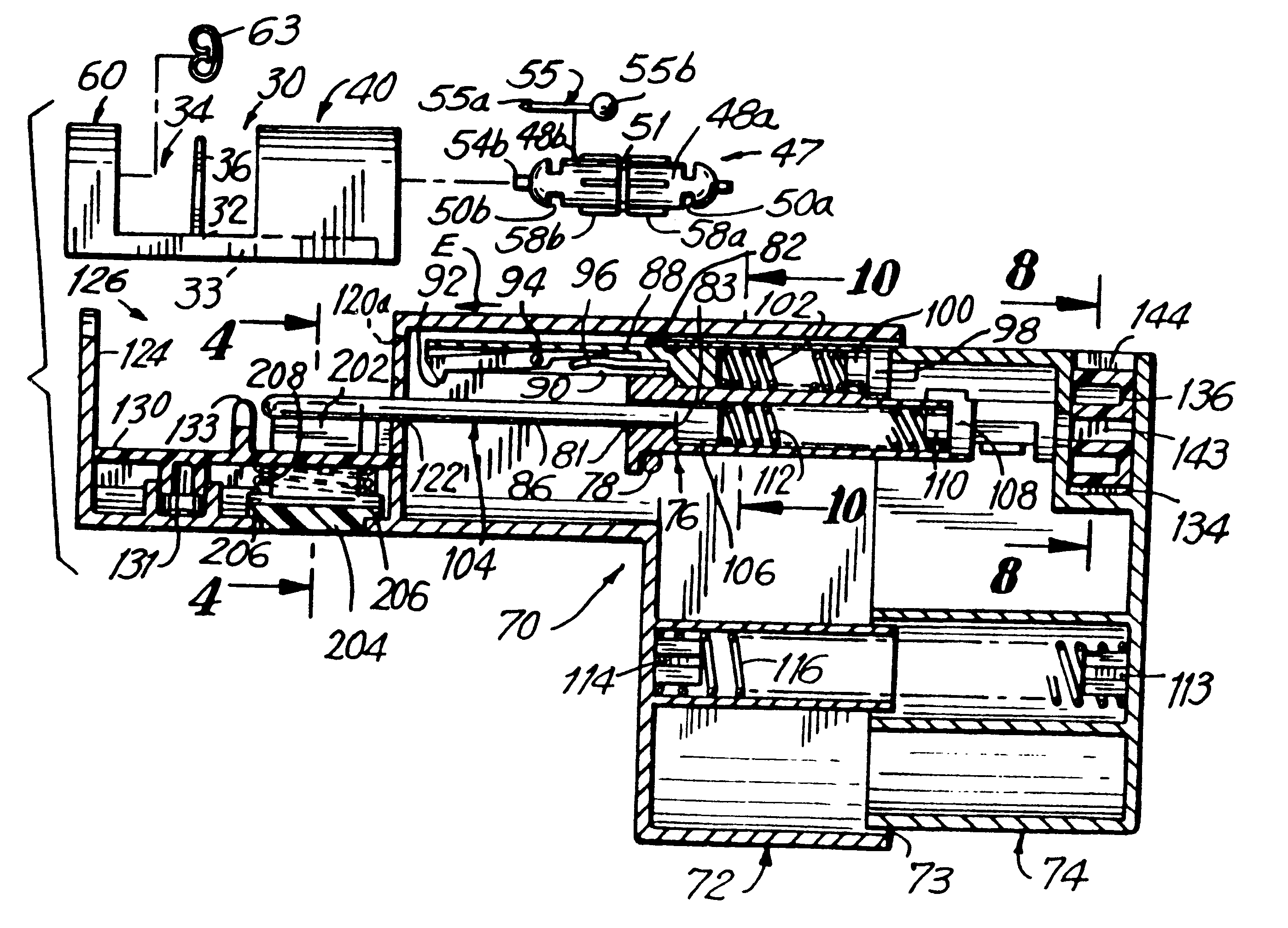
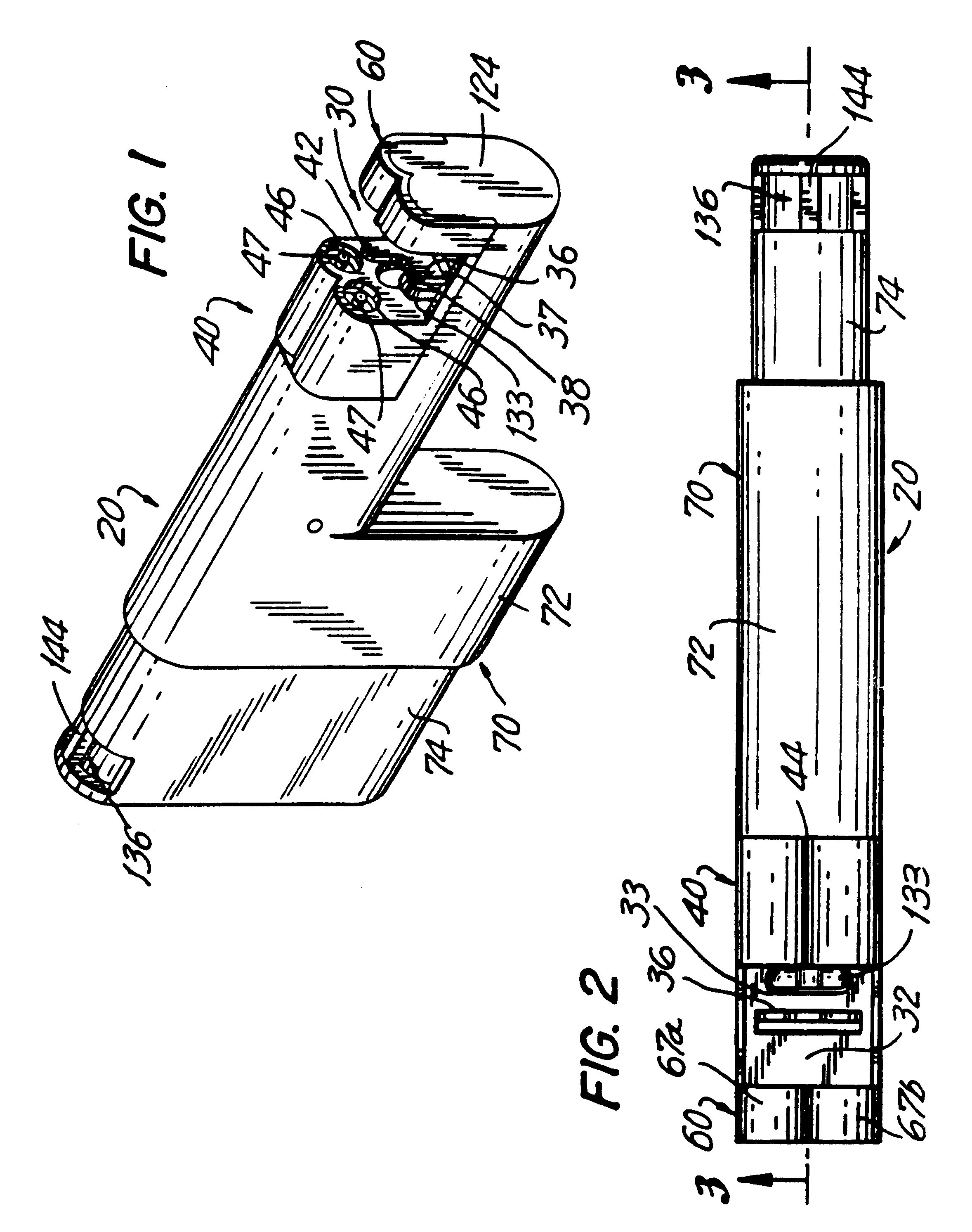
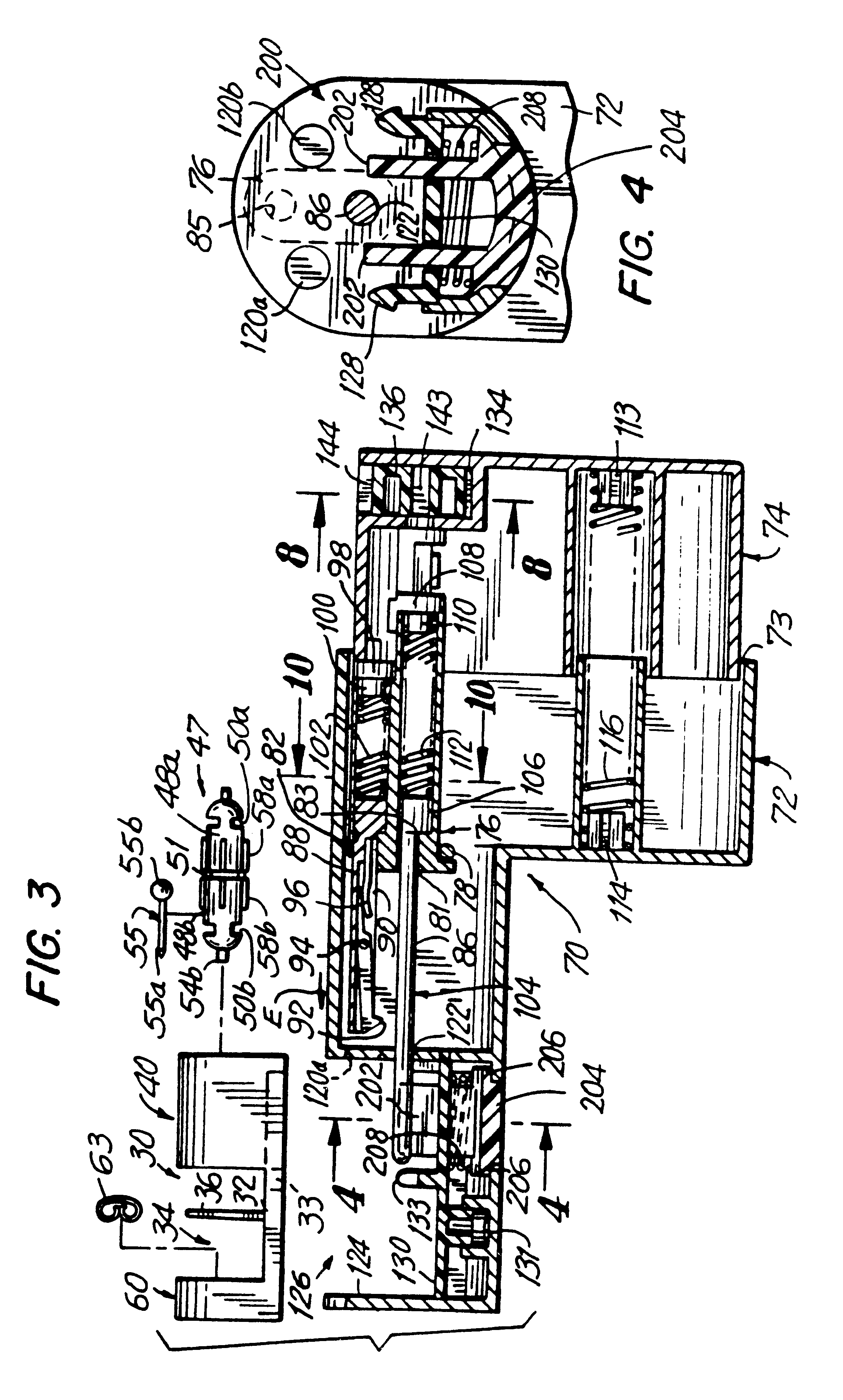
Reference is now had to FIGS. 1-6 wherein an ear piercing assembly, constructed in accordance with a preferred embodiment of the instant invention, and generally indicated as 20, is depicted. Ear piercing assembly 20 includes a unitary ear piercing earring ("earring") and clutch cartridge assembly ("cartridge assembly") 30 and an ear piercing instrument generally indicated as 70. Cartridge assembly 30 includes an ear piercing earring retaining sub-assembly 40 and a clutch retaining sub-assembly, generally indicated as 60.

Cartridge assembly 30 is formed as an integral molded piece. Earring retaining sub-assembly 40 is separated from clutch retaining sub-assembly 60 by a floor 32 forming a saddle region 34 therebetween. A pivotable clamp 36 is affixed to floor 32 within saddle region 34. A hinge 37 is formed between the clamp 36 and floor 32 allowing movement of clamp 36 towards clutch retaining sub-assembly 60. Floor 32 is formed with a slot 33 therein.

Earring retaining sub-assembly ...


PUM


Abstract

An ear piercing assembly includes a disposable cartridge assembly including a first and second ear piercing earring and an ear piercing earring retaining sub-assembly for releaseably supporting the ear piercing earring therein. A clutch retaining sub-assembly is integrally formed with the ear piercing earring retaining sub-assembly and releaseably supports a first and second clutch therein. An ear piercing instrument is adapted to receive the cartridge assembly and includes a plunger assembly for ejecting an ear piercing earring from the ear piercing earring retaining sub-assembly and is displaceable for selectively moving between a first position for ejecting the first ear piercing earring from the ear piercing earring retaining sub-assembly and a second position for ejecting the second ear piercing earring from the ear piercing earring retaining sub-assembly.

Description

BACKGROUND OF THE INVENTIONThis invention is directed to a disposable earlobe piercing earring and clutch cartridge and instrument for use therewith and in particular, to an earlobe piercing assembly for facilitating earlobe piercing and maintaining the piercing earring sterile during handling, storage and piercing.The most recent prior art ear piercing systems are of two types, namely cartridge housed earrings and open earrings. Both types operate by inserting a pointed earring or stud through the earlobe. This earring remains in place four to six weeks until the hole produced is healed.The cartridge housed earring systems utilize either a cartridge housing a single piercing earring and clasp, requiring two cartridges per pair of earrings; a separate cartridge for each earring and clasp requiring four cartridges per pair of earrings; or no cartridge, but instead earrings and clasps which are unprotected and inserted into the piercing instrument from a carrier block. In all cases ex...

Claims


Application Information

Patent Timeline
IPC IPC(8): A44C7/00
CPCA44C7/001
Inventor MANN, SAMUEL J.
Owner INVERNESS CORPROATION
Learn More