
Cam for a windrow merger and pickup head having a variable radius

a technology of windrow and head, which is applied in the direction of mowers, agricultural tools and machines, and mowers, etc., can solve the problems of affecting the smooth operation of the machine, so as to reduce the radius to the axis of rotation, reduce the speed of rotation, and facilitate the handling of the material.

Active Publication Date: 2018-06-19
OXBO INT CORP
View PDF119 Cites 1 Cited by
  • Summary
  • Abstract
  • Description
  • Claims
  • Application Information

AI Technical Summary

Benefits of technology

The patent describes a cam design for a pickup assembly that helps in handling and spreading material gently. The cam has a decreasing radius in the front and an increasing radius towards the top, which slows down the tines and allows for smooth pickup of material from the ground. This also helps in propelling the material at a greater distance and spreading it more evenly over the conveyor belts. The design also minimizes clumping and allows for faster operating and increased capacity.

Problems solved by technology

Although mergers generally perform in a satisfactory manner and provide satisfactory pickup and conveyance into windrows, for certain conditions, problems may occur.
If the speed of the tines at the top of the rotation when the picked up material is propelled rearward is too slow, the material may simply fall off the tine or only be propelled to the front portion of the belt so that clumping may occur.
However, if the speed is increased to pick up and propel wet or heavier material from the ground, the tines move quickly at the point of engagement and lifting from the ground.
At these higher speeds at the point of engagement, the material tends to be propelled forward, making it more difficult to pick up.
Higher engagement speeds may damage the material being picked up and lessen its nutritional value.
Moreover, in order to avoid higher speeds, it may be necessary to advance the merger more slowly along the field, thereby decreasing capacity and performance.

Method used


Image

  • Cam for a windrow merger and pickup head having a variable radius
  • Cam for a windrow merger and pickup head having a variable radius
  • Cam for a windrow merger and pickup head having a variable radius

Examples


Embodiment Construction

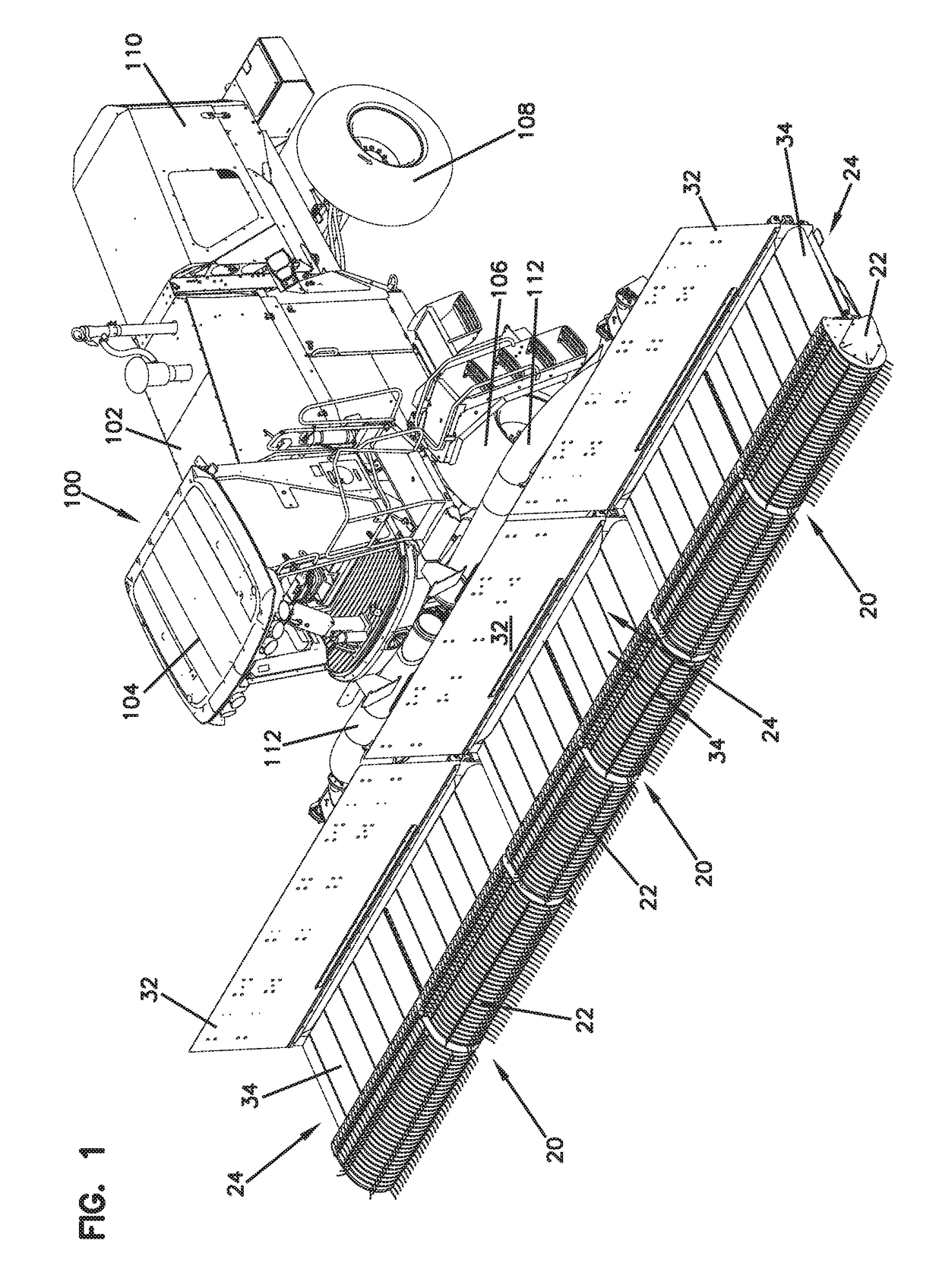
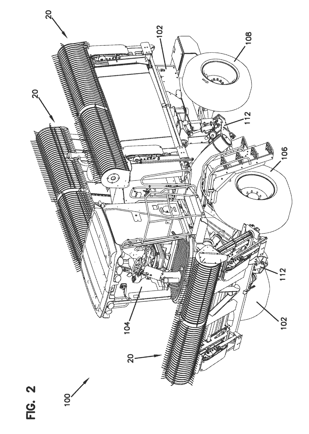
[0033]Referring now to the drawings and in particular to FIGS. 1-3, there is shown a merger apparatus, generally designated (100). In the embodiment shown, the merger apparatus (100) is a self-propelled merger. However, it can be appreciated that the principles of the present invention also apply to a tow-behind merger (200), such as shown in FIGS. 11-18. In the embodiments shown, the merger has three pickup and transfer assemblies (20). However, the present invention is also applicable to configurations with more or fewer pickup and transfer assemblies.

[0034]The merger apparatus (100) includes a chassis (102) and an operator cab (104) at a front of the chassis, and three pickup and transfer assemblies (20). The cab (104) includes the steering and the other controls for driving the merger and operating the pickup and transfer assemblies (20). In the embodiment shown, the merger chassis (102) is supported on front drive wheels (106) and rear wheels (108). The merger (100) includes a ...


PUM


Abstract

A windrow merger includes heads having cams that control the speed of the tines. The cam is configured with a section that slows the speed of the tines while passing a lower front portion of the path of rotation to lift material from the ground at lower speeds and therefore handles the material more gently at the point of pickup. The cam is configured to accelerate the tines at the point where the lifted material is propelled rearward from the pickup assembly. The merger heads also include a widened conveyor that is configured with an upper surface extending rearward and slightly downward to further evenly distribute material across the width of the conveyor. The heads are supported on skids that have a linkage connecting the skids at each end of the head with one of the skids having a mechanism that acts as a master to control the slave of the linked opposite skid.

Description

BACKGROUND OF THE INVENTION[0001]Field of the Invention[0002]The present invention relates to a windrow merger apparatus and a method of merging windrows, and in particular relates to a windrow merging apparatus with a head having cams that slow the tines during pick up and speed the tines when releasing material.[0003]Description of the Prior Art[0004]Devices for merging windrows in the field are well known to gather material such as cut hay, alfalfa and other crops that might be merged into windrows for further processing such as chopping and / or harvesting. Windrow mergers typically include one or more heads to move the material to a single row at one side of the merger. Such mergers typically include tines that rotate and pick up the material from the ground and throw it rearward onto aligned conveyors that convey the material laterally to form a windrow.[0005]Although mergers generally perform in a satisfactory manner and provide satisfactory pickup and conveyance into windrows,...

Claims


Application Information

Patent Timeline
Patent Type & Authority Patents(United States)
IPC IPC(8): A01D34/00A01D89/00A01D84/00
CPCA01D89/003A01D89/002A01D84/00A01D89/005
Inventor LEISTON, MICHAEL T
Owner OXBO INT CORP
Learn More