
Dual mode flow control valve

a flow control valve and dual-mode technology, applied in fluid pressure control, pressure relieving devices on sealing faces, instruments, etc., can solve the problems of inability of controllers to eliminate such wide swings that are inherent in the system, inconvenient mounting, and insufficient flow in some terminals. , to achieve the effect of improving electropneumatic control

Active Publication Date: 2018-06-05
KELLY EDMUND F
View PDF5 Cites 1 Cited by
  • Summary
  • Abstract
  • Description
  • Claims
  • Application Information

AI Technical Summary

Benefits of technology

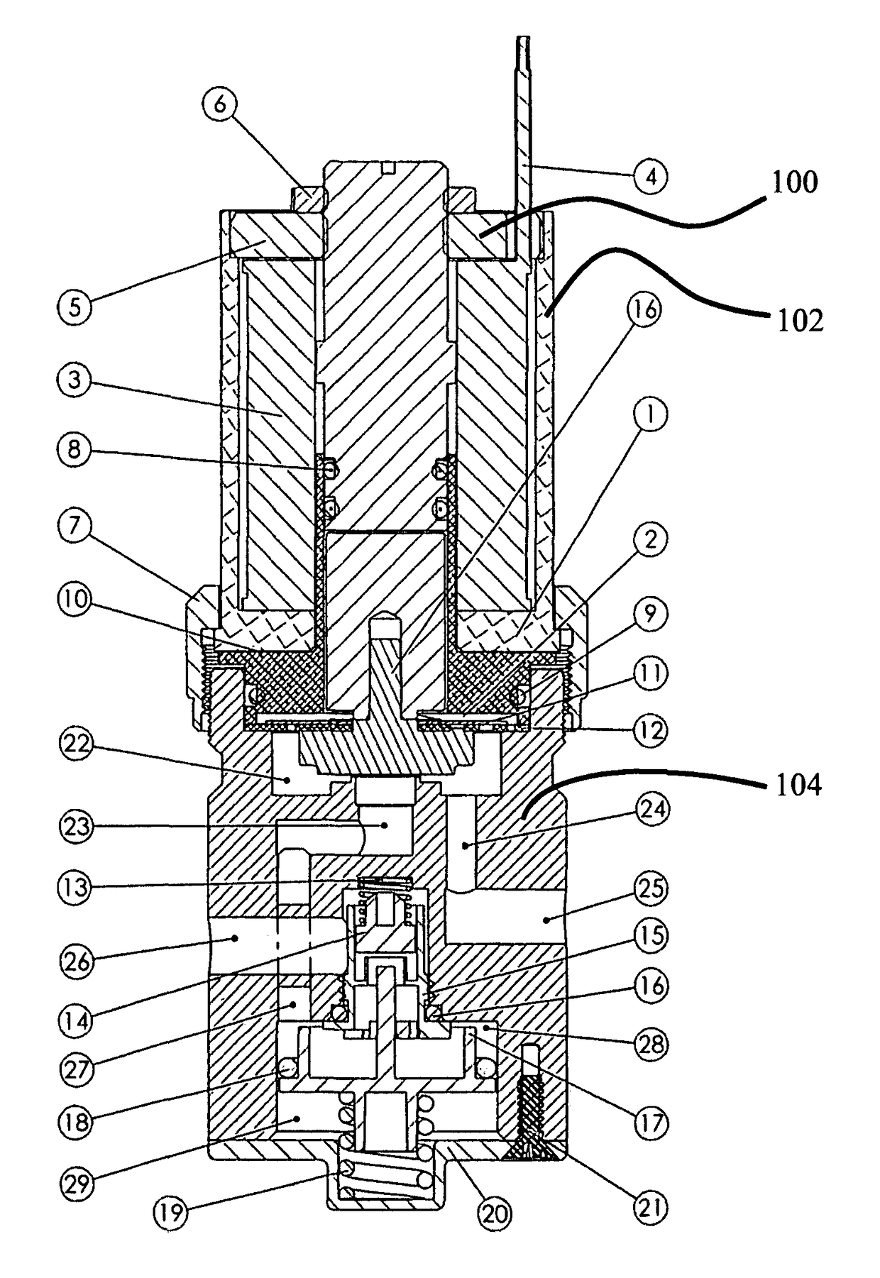
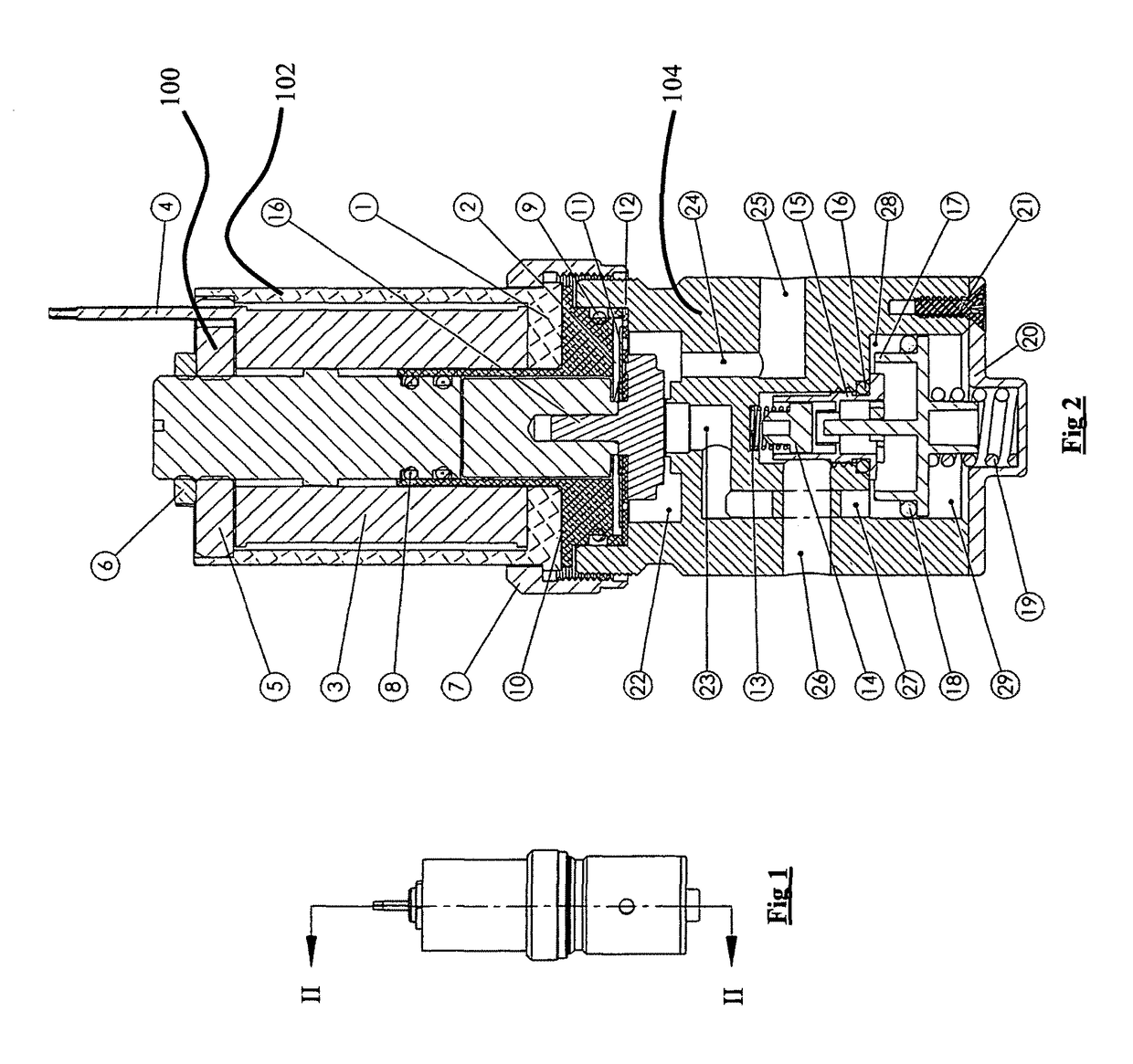
The present invention relates to a small and lightweight control mechanism that is insensitive to position and vibration. This device can be used as a main flow control valve for various medical products. The invention is well adapted for use as a control mechanism for valves in process lines. The technical effects of the invention are that it allows for precise control of valves in a compact and durable package.

Problems solved by technology

While such designs can be very efficient in terms of minimizing pressure drop across the vales, if the correct balancing of the system is not established an unequal distribution of the flow results such that there will be a surplus flow in some of the terminals and an inadequate flow in others.
The result of this will be that desired distribution cannot be assured throughout the system.
To control such a system with PID controllers to eliminate such wide swings that are inherent within the system remains very difficult.
Disadvantages include a limited sizes, since with a large unbalanced valve the forces needed to seat and hold the flow often becomes impractical.
However, such a solution creates an additional leak path and at a cost that is generally higher.
In trim control applications, the selection of balanced or unbalanced designs is not entirely straightforward, and will ultimate be based upon the selection and design of the actuator.

Method used


Image

  • Dual mode flow control valve
  • Dual mode flow control valve

Examples


Embodiment Construction

[0014]The best mode for carrying out the invention is presented in terms of its preferred embodiment, herein depicted within the Figures.

1. Detailed Description of the Figures

[0015]Further for purposes of the present application and for convenience, certain terms employed in the specification, examples, and appended claims are collected here. Unless defined otherwise, all technical and scientific terms used herein have the same meaning as commonly understood by one of ordinary skill in the art to which this invention belongs.

[0016]The articles “a” and “an” are used herein to refer to one or to more than one (i.e., to at least one) of the grammatical object of the article. By way of example, “an element” means one element or more than one element.

[0017]The terms “comprise,”“comprising,”“include,”“including,”“have,” and “having” are used in the inclusive, open sense, meaning that additional elements may be included. The terms “such as”, “e.g.”, as used herein are non-limiting and are ...


PUM


Abstract

An electropneumatic proportional flow control device improves electropneumatic control of pneumatically operated valves. A single integrated valve incorporates a proportional valve component in operational and physical coordination with a pressure regulator valve component. The flow path of fluid is initially passed through the regulator component whereby pressure is regulated to within a manageable range for operation of a balanced type proportional valve component.

Description

FIELD OF THE INVENTION[0001]The present invention relates generally to a device for electropneumatic control of pneumatically operated valves and, more specifically to such a valve having an armature and method of operation such as to allow improved turndown ratios.BACKGROUND OF THE INVENTION[0002]Numerous types of proportional pneumatic flow control valves are presently available which accurately control flow over a wide range of flow control applications. Two broad categories of such devices can be identified that included balanced valve designs, and unbalanced valve designs.[0003]Balanced values are, in general, maintain the controlled fluid flow rate at a relatively constant rate (i.e., “balanced”) in spite of pressure changes. Used in fluid distribution systems (most commonly for water and air distribution), such balanced values are calibrated to a specific range, and their accuracy is dependent upon the total range of capable flow, which is otherwise known as the “Full Scale” ...

Claims


Application Information

Patent Timeline
IPC IPC(8): F16K31/06F16K39/02F16K31/122
CPCF16K31/0693F16K39/02F16K31/0655F16K31/0696F16K31/0624F16K31/0689F16K31/1221F16K39/026G05D16/2033G05D16/107G05D16/2022
Inventor KELLY, EDMUND F.
Owner KELLY EDMUND F
Learn More