
Network filtering circuit for protection lightning surge

a network filtering circuit and lightning surge technology, applied in the direction of preventing network interference, emergency protective arrangements for limiting excess voltage/current, electrical equipment, etc., can solve problems such as network chip damag

Active Publication Date: 2018-05-22
FOXCONN INTERCONNECT TECH LTD
View PDF21 Cites 33 Cited by
  • Summary
  • Abstract
  • Description
  • Claims
  • Application Information

AI Technical Summary

Benefits of technology

[0002]The present invention relates to a network filtering circuit, and more particularly to a network filtering circuit for protection lightning surge.
[0004]U.S. Pat. No. 8,272,898 discloses a network filtering circuit including a cable side, a physical side, and a plurality of transmission channels connected therebetween. Each of the transmission channels includes an isolation transformer with a primary coil connected to the cable side and a second coil connected to a common mode choke wherein the other side of the common mode choke is connected to the physical side. The primary coil has a center tap series connection with a capacitor and a resistor to a ground node. A surge would follow from the cable side to the ground node through the capacitor and the resistor, when the cable side is bearing a lightning. The capacitor and the resistor maybe damaged by the surge, after that the surge maybe coupled to the secondary coil from the primary coil and conducted to the physical side which has a network chip, therefore the network chip may be damaged by the surge.

Problems solved by technology

The capacitor and the resistor maybe damaged by the surge, after that the surge maybe coupled to the secondary coil from the primary coil and conducted to the physical side which has a network chip, therefore the network chip may be damaged by the surge.

Method used


Image

  • Network filtering circuit for protection lightning surge
  • Network filtering circuit for protection lightning surge

Examples


Embodiment Construction

[0010]Reference will now be made in detail to some preferred embodiments of the present invention.

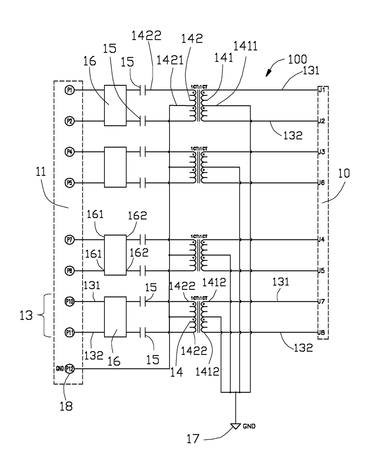
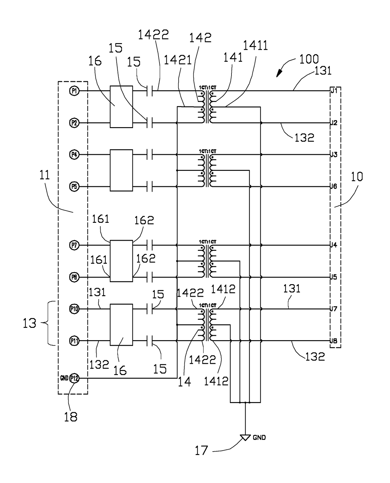
[0011]Referring to FIG. 1, a network filtering circuit 100 according to the invention. The network filtering circuit 100 includes a cable side 10 for connection with a network cable, a physical side 11 for connection with a mother board, and a plurality of transmission channels 13 connected between the cable side 10 and the physical side 11. Each of the transmission channels 13 includes a first transmission wire 131 and a second transmission wire 132 for transmitting a pair of different signals.

[0012]Each of the transmission channels 13 has an isolation transformer 14, a common mode choke 16, and a pair of capacitors 15 connected therebetween. The isolation transformer 14 has a primary coil 141 connected with the cable side 10 and a secondary coil 142 coupling with the primary coil 141. The primary coil 141 includes a first center tap 1411 directly connected to a first ground node 17 an...


PUM


Abstract

The network filtering circuit includes a cable side for connection with a network cable, a physical side for connection with a mother board, and a plurality of transmission channels connected between the cable side and the physical side. Each of the transmission channels includes an isolation transformer with a primary coil connected with the cable side and a secondary coil coupling with the primary coil. A common mode choke has two first ends connected to the physical side and two opposite second ends. A pair of capacitors series connection with the corresponding second ends and are connected between the secondary coil and the common mode choke. The primary coil has a first center tap directly connected to a ground node.

Description

BACKGROUND OF THE INVENTION[0001]1. Field of the Invention[0002]The present invention relates to a network filtering circuit, and more particularly to a network filtering circuit for protection lightning surge.[0003]2. Description of Related Arts[0004]U.S. Pat. No. 8,272,898 discloses a network filtering circuit including a cable side, a physical side, and a plurality of transmission channels connected therebetween. Each of the transmission channels includes an isolation transformer with a primary coil connected to the cable side and a second coil connected to a common mode choke wherein the other side of the common mode choke is connected to the physical side. The primary coil has a center tap series connection with a capacitor and a resistor to a ground node. A surge would follow from the cable side to the ground node through the capacitor and the resistor, when the cable side is bearing a lightning. The capacitor and the resistor maybe damaged by the surge, after that the surge m...

Claims


Application Information

Patent Timeline
Patent Type & Authority Patents(United States)
IPC IPC(8): H03H7/09H03H7/01H02H9/00H03H7/42
CPCH03H7/0115H02H9/005H03H7/427H03H7/09H03H7/0138
Inventor XU, YONG-CHUN
Owner FOXCONN INTERCONNECT TECH LTD
Learn More