Electromagnetic device for stabilizing and reducing the deformation of a strip made of ferromagnetic material, and related process
a technology of ferromagnetic material and electrode, which is applied in the direction of roll mill control device, manufacturing tools, transportation and packaging, etc., can solve the problems of reducing the effectiveness of action, non-uniform distribution of coating, and strong disturbance of feeding stability of metal strips, so as to reduce the vibration of ferromagnetic strips, eliminate liquid metal leakage, and reduce the deformation of strips made.
- Summary
- Abstract
- Description
- Claims
- Application Information
AI Technical Summary
Benefits of technology
Problems solved by technology
Method used
Image
Examples
first embodiment
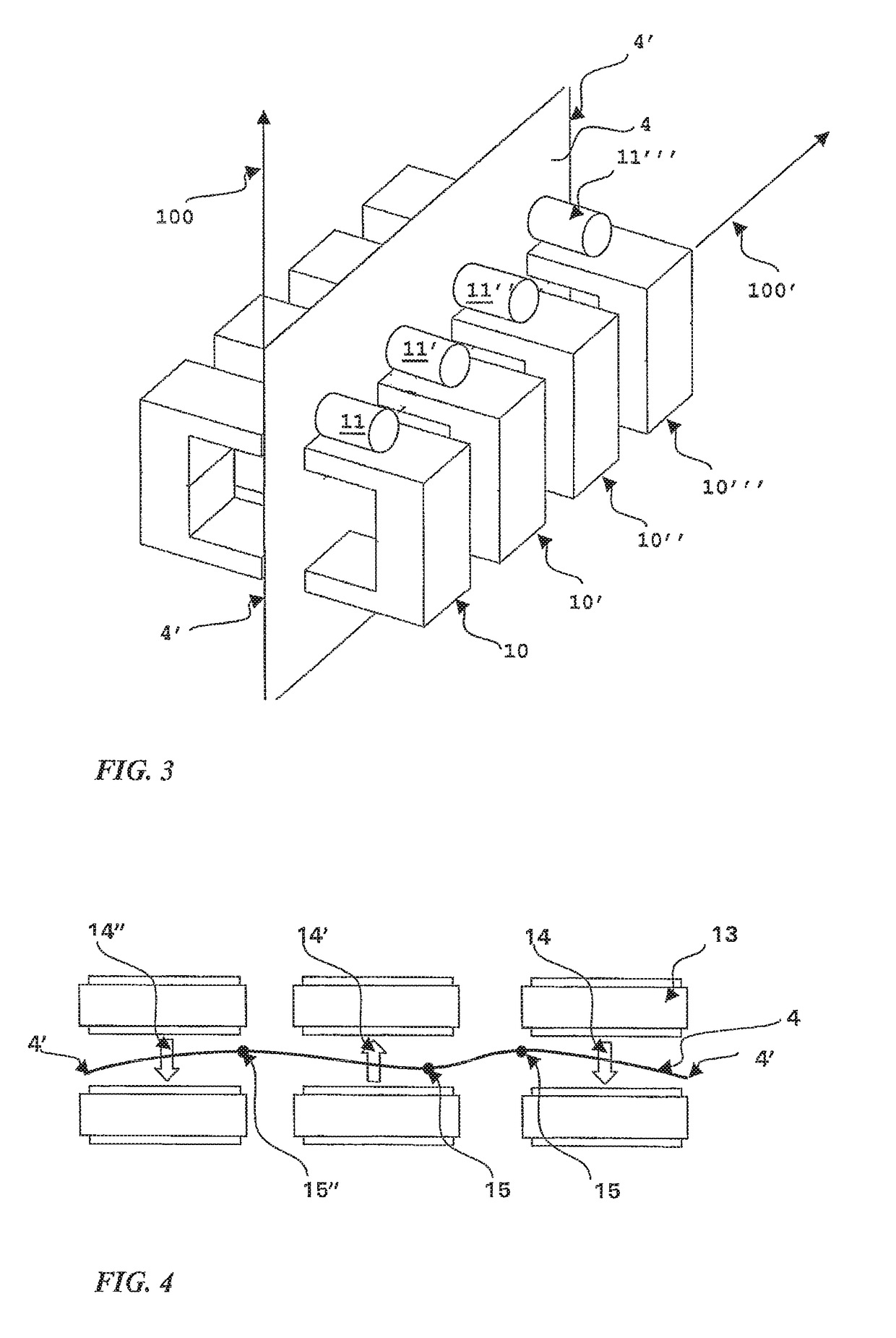
[0045]FIG. 8 is a schematic view relating to device 1 according to the present invention. The first connection element 26 and the second connection element 26′ are preferably made in the shape of a bar with a rectangular section, made of ferromagnetic material, which is laminated or not laminated. As indicated above, the two connection elements 26, 26′ have a mirroring position with respect to the theoretical plane 50 and are arranged so that the longitudinal axis 103 thereof is parallel to the transversal alignment direction 100′ of the electromagnets 15, 15′, 15″, 15′″, 16, 16′, 16″, 16′″, i.e. orthogonal to the transportation direction 100 of strip 4. In particular, according to a preferred embodiment, the two connection elements 26, 26′ have an extension measured along said transversal direction 100′, which is greater than or equal to the extension of strip 4 measured along said transversal direction.
[0046]The first connection element 26 serves the purpose of conveying and distr...
second embodiment
[0059]FIGS. 16 and 17 relate to a device according to the present invention. In this case, device 1 comprises a first connection body 27 which connects the yokes 19 of the first electromagnets 15, 15′, 15″, 15′″ to each other.
[0060]Device 1 also comprises a second connection body 27′ which connects the yokes 19 of the second electromagnets 16, 16′, 16″, 16′″ to each other. In particular, the first connection body 27 connects the rear sections of the yokes 19 of the first electromagnets 15, 15′, 15″, 15′″ to each other. The expression “rear section” in essence means the section of the yoke farthest from the theoretical pass-line 50. As shown in top view in FIG. 16, the second connection body 27′ connects the rear sections of the yokes 19 of the second electromagnets 16, 16′, 16″, 16′″ in an entirely similar way.
[0061]FIGS. 20 and 21 are side views which show the configuration of an electromagnet relating to the electromagnetic device shown in FIGS. 16 and 17. In particular, FIG. 20 s...
PUM
| Property | Measurement | Unit |
|---|---|---|
| distance | aaaaa | aaaaa |
| distance | aaaaa | aaaaa |
| thickness | aaaaa | aaaaa |
Abstract
Description
Claims
Application Information
 - R&D
- Intellectual Property
- Life Sciences
- Materials
- Tech Scout
- Unparalleled Data Quality
- Higher Quality Content
- 60% Fewer Hallucinations
Browse by: Latest US Patents, China's latest patents, Technical Efficacy Thesaurus, Application Domain, Technology Topic, Popular Technical Reports.
© 2025 PatSnap. All rights reserved.Legal|Privacy policy|Modern Slavery Act Transparency Statement|Sitemap|About US| Contact US: help@patsnap.com


