
System, method and apparatus for cementless retention of dental crowns to implants

a technology of dental crowns and implants, applied in dental implants, dental surgery, medical science, etc., can solve the problems of loss of implants, inability to provide proper cosmetics, and difficulty in removing cementless crowns for any required maintenan

Inactive Publication Date: 2018-05-15
KULICK WALTER KENNEDY
View PDF13 Cites 2 Cited by
  • Summary
  • Abstract
  • Description
  • Claims
  • Application Information

AI Technical Summary

Benefits of technology

The present invention provides a dental abutment and a dental crown for attachment to a dental implant in a patient's alveolar arch. The abutment includes a cylindrical post extending upwardly from a base with a bore defined through the post and the base, and a threaded aperture in the top surface of the base. The abutment can be securely attached to the dental implant by a screw. The dental crown includes a mount with a cavity to conform to the abutment, an orifice at the posterior end of the mount, and a threaded aperture to secure the crown to the abutment. The dental implant secured in the patient's alveolar arch can also be used to secure the dental crown. The technical effects of this invention include improved stability and secure attachment of dental crowns to dental implants, and simplified procedures for replacement or restoration of teeth.

Problems solved by technology

Due to the angle between the alveolus and the alignment of most anterior teeth and some posterior teeth, screw retention of crowns to current abutments would require access through the front of the crown or another location that would not provide proper cosmetic results.
The cemented crown is not easily removable for any required maintenance.
In addition, the implant site often reacts adversely to cement which may lead to the loss of the implant.
If the retaining screw loosens, destruction of the crown to gain access to the abutment retaining screw is required.

Method used


Image

  • System, method and apparatus for cementless retention of dental crowns to implants
  • System, method and apparatus for cementless retention of dental crowns to implants
  • System, method and apparatus for cementless retention of dental crowns to implants

Examples


Embodiment Construction

[0021]The following detailed description is of the best currently contemplated modes of carrying out exemplary embodiments of the invention. The description is not to be taken in a limiting sense, but is made merely for the purpose of illustrating the general principles of the invention, since the scope of the invention is best defined by the appended claims.

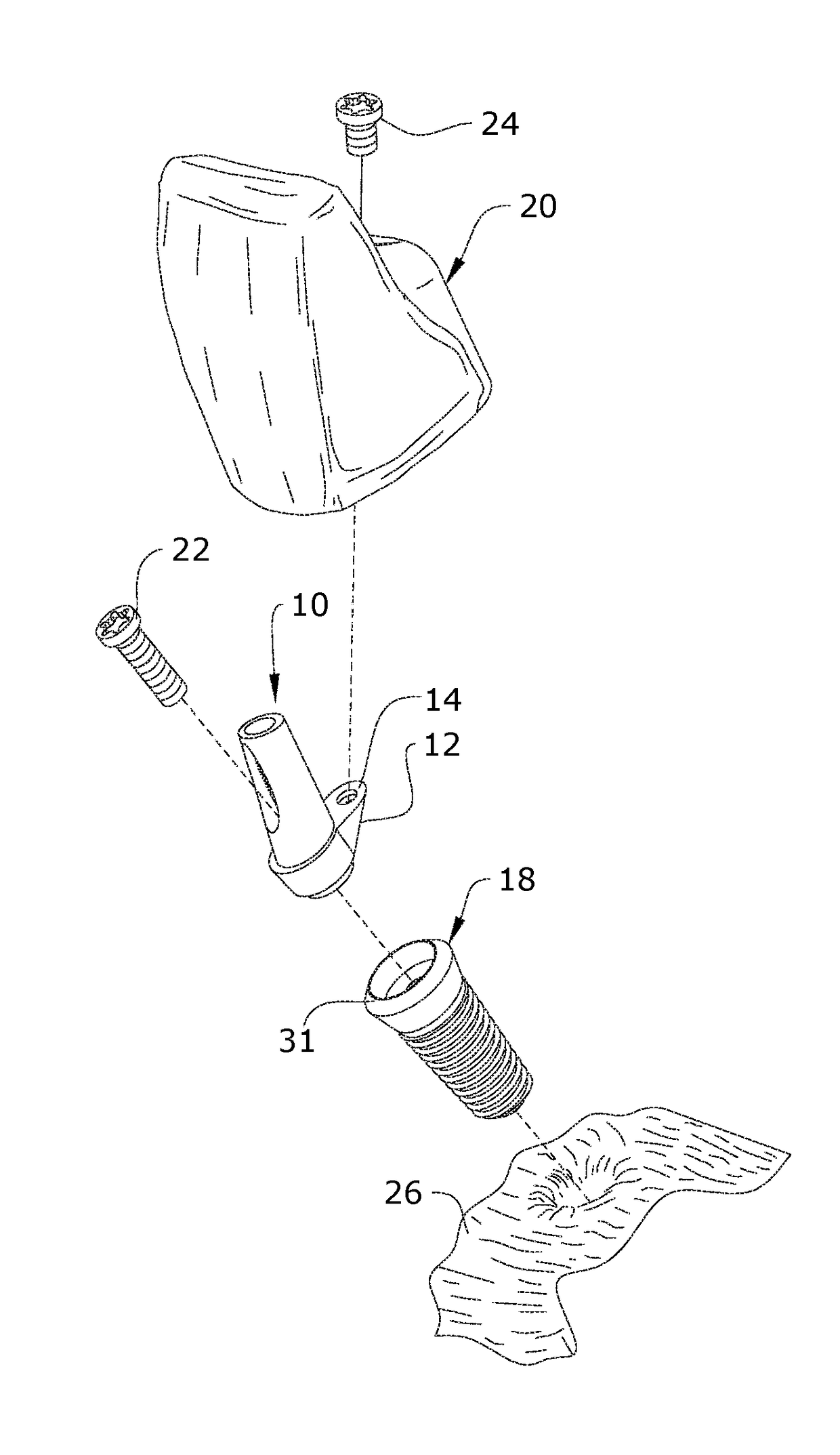
[0022]Broadly, an embodiment of the present invention provides system, method and apparatus for the surgical implantation of a crown 20 for an tooth into a patient's alveolar arch 28.

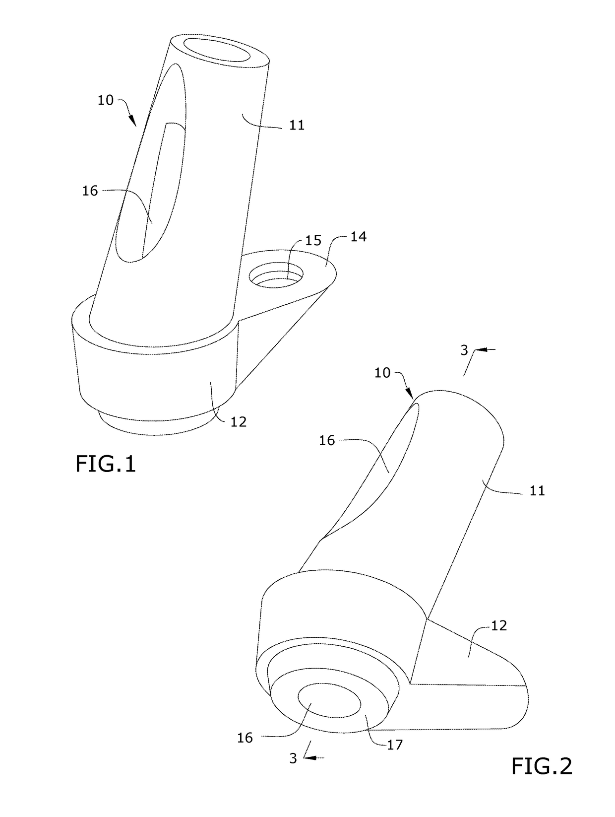
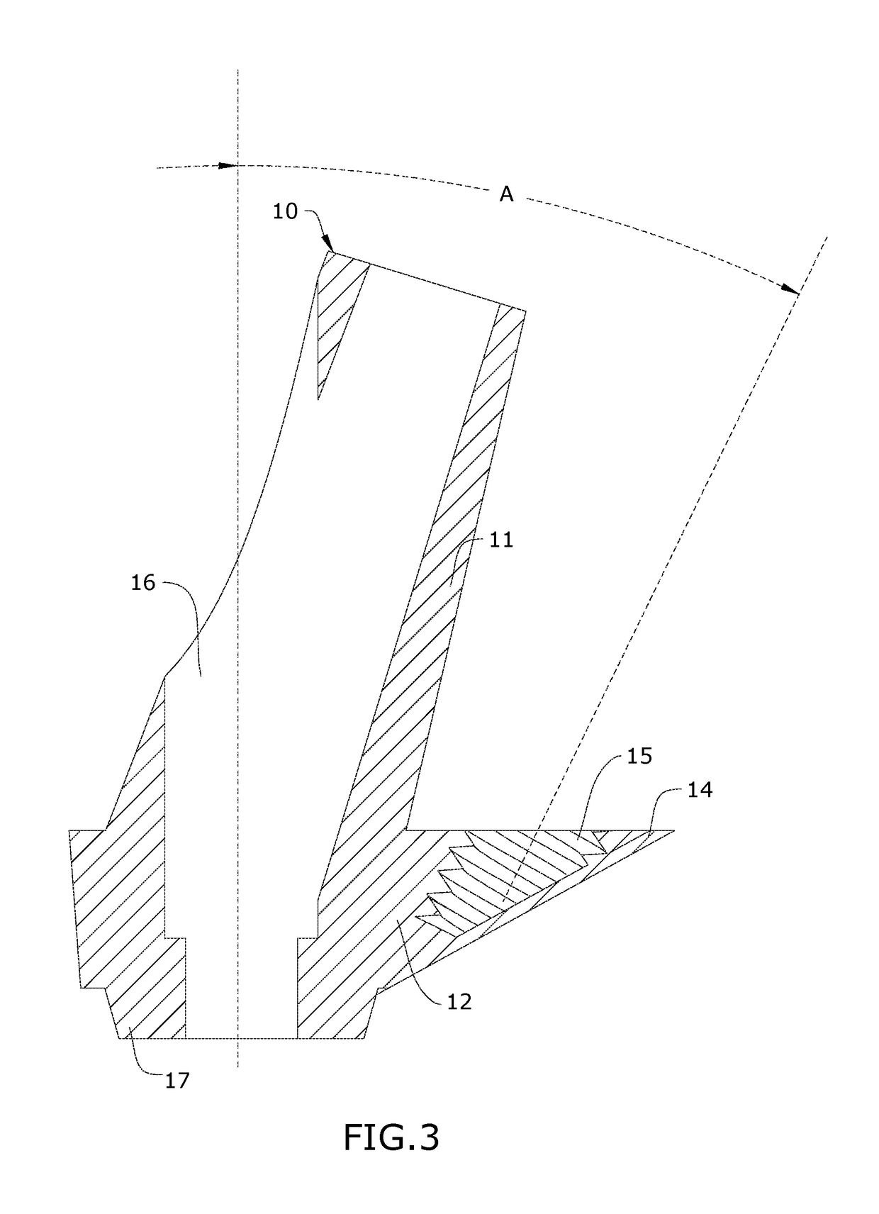
[0023]An abutment 10 according to aspects of the invention, includes a generally cylindrical post 11 extending upwardly from a base 12. The post 11 includes a bore 16 that is defined through an anterior portion of the post 11 and extends through the base 12. The bore 16 is defined at an angle that is anteriorly offset from a vertical axis of the post 11. The bore 16 is axially aligned with a longitudinal axis of an implant 18.

[0024]The implant 18 ha...


PUM


Abstract

A system, method and apparatus for dental of an anterior tooth. The system includes an abutment having a generally cylindrical post extending from a base. A bore is defined through an anterior face of the post and extends through the base. A protrusion extends from an aft end of the base and is configured to receive a threaded fastener to secure a crown to the abutment. The abutment is secured to a dental implant via a screw extending through the bore into the implant.

Description

BACKGROUND OF THE INVENTION[0001]The present invention relates to dental implants that are inserted into the alveolar bone and, more particularly, to dental implants for anterior teeth.[0002]Dental implants are typically achieved with the surgical implantation of an implant into the patient's alveolar arch and open to the gum line. The implant performs the role of the root structure of a natural tooth to secure a crown of a natural tooth to the patient's jaw. In current practice, a device called an abutment is secured with a retaining screw to the implant to provide a post structure above the gum line to which the crown is then attached, typically by cementation.[0003]Due to the angle between the alveolus and the alignment of most anterior teeth and some posterior teeth, screw retention of crowns to current abutments would require access through the front of the crown or another location that would not provide proper cosmetic results. Accordingly, due to this misalignment, current c...

Claims


Application Information

Patent Timeline
IPC IPC(8): A61C8/00
CPCA61C8/0068A61C8/0056A61C8/0054A61C8/0022A61C8/0048
Inventor KULICK, WALTER KENNEDY
Owner KULICK WALTER KENNEDY
Learn More