
Image forming apparatus, and method for controlling image forming apparatus

a technology of image forming apparatus and forming apparatus, which is applied in the direction of electrographic process, instruments, high-level techniques, etc., can solve the problems of reducing user's convenience, and taking time to perform initialization

Active Publication Date: 2018-05-01
CANON KK
View PDF14 Cites 0 Cited by
  • Summary
  • Abstract
  • Description
  • Claims
  • Application Information

AI Technical Summary

Problems solved by technology

Thus, it takes time to perform initialization such as energization, software initialization, or hardware pre-processing.
As a result, it takes time to start the printer device, the scanner device, and the FAX device, and performance of processing is delayed by the time, resulting in decreasing user's convenience.
Thus, it takes time to perform initialization such as hardware pre-processing, although energization and software initialization have ended.
As a result, it takes time to start the printer device and the scanner device, and the execution of processing is delayed by the time, resulting in decreasing user's convenience.
Thus, a user attempts unsuccessfully to immediately use the image forming apparatus, thereby resulting in decreasing user's convenience.
However, when the copy screen is not set as the initial screen, the scanner driver and the printer driver remain not powered on.
Therefore, when the copy screen is not set as the initial screen, a user attempts unsuccessfully to immediately use the image forming apparatus, thereby resulting in decreasing user's convenience.

Method used


Image

  • Image forming apparatus, and method for controlling image forming apparatus
  • Image forming apparatus, and method for controlling image forming apparatus
  • Image forming apparatus, and method for controlling image forming apparatus

Examples


Embodiment Construction

[0034]Exemplary embodiments will be described below with reference to the drawings.

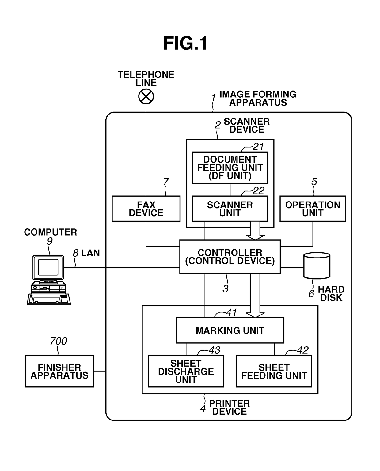
[0035]FIG. 1 is a block diagram illustrating a configuration of an image forming system according to a first exemplary embodiment. In FIG. 1, a multifunction peripheral including devices that respectively execute a print function, a scanner function, and a data communication function is taken as an example.

[0036]In FIG. 1, an image forming apparatus 1 receives a job from a computer 9 via a local area network (LAN) 8. More than one computer can be connected to the image forming apparatus 1.

[0037]A scanner device 2 optically reads an image from a document and converts the read image into a digital image. A printer device 4 outputs the digital image from the scanner device 2 to a sheet. An operation unit 5 includes a touch panel and hardware keys for receiving a setting for the image forming apparatus 1 from a user and displaying a processing status. A hard disk 6 stores, among other information, the dig...


PUM


Abstract

An image forming apparatus that shifts to a power saving state, includes a printing unit, a printing control unit configured to control the printing unit, and a power supply unit configured to supply power to the printing control unit when the image forming apparatus returns from the power saving state, wherein the printing control unit, to which power is supplied by the power supply unit, executes initialization of the printing unit in a case where a printing screen for performing a printing function is set as a initial screen to be displayed when the image forming apparatus returns from the power saving state, and wherein the printing control unit does not execute initialization of the printing unit in a case where a selection screen for selecting the printing function is set as a initial screen to be displayed when the image forming apparatus returns from the power saving state.

Description

BACKGROUND[0001]Field[0002]Aspects of the present invention generally relate to an image forming apparatus and a method for controlling the image forming apparatus.[0003]Description of the Related Art[0004]A method for energizing a printer device, a scanner device, and a facsimile (FAX) device in an image forming apparatus when a user is found to use the printer device, the scanner device, and the FAX device due to an improvement in power saving function has been proposed.[0005]For example, the scanner device is energized only when a scan function is used, the printer device is energized only when a print function is used, and the FAX device is energized only when a FAX function is used. Simultaneously, boards and chips respectively related to the printer device, the scanner device, and the FAX device are energized only when used.[0006]In a method for energizing a printer device, a scanner device, and a FAX device in an image forming apparatus when a user uses the devices, the image...

Claims


Application Information

Patent Timeline
Patent Type & Authority Patents(United States)
IPC IPC(8): G06K15/00G06F1/32G03G15/00H04N1/00
CPCH04N1/00896G03G15/5004H04N1/00474G06F1/3284Y02D10/159Y02D50/20H04N2201/0094H04N1/00411H04N1/00928Y02D10/00Y02D30/50B41J29/38
Inventor HIKICHI, ATSUSHI
Owner CANON KK
Learn More