Reduced-friction joint with electromagnetically separable bearing surfaces

a bearing surface and electromagnetically separable technology, applied in hip joints, prostheses, medical science, etc., can solve the problems of increasing the risk of implant failure, the current design of total joint replacement (“tjr”) is not optimal for the increasing population, and the patient's life is more likely to be affected, so as to reduce the production of wear particles, promote fluid-film lubrication, and reduce the friction between bearing surfaces

Active Publication Date: 2018-05-01
HOWARD JASON
View PDF12 Cites 7 Cited by
  • Summary
  • Abstract
  • Description
  • Claims
  • Application Information

AI Technical Summary

Benefits of technology

The patent describes a magnetic bearing system for reducing wear particle production in joint replacement devices. The system uses electromagnetic induction principles to create a repulsive force between the bearing surfaces, reducing friction between them. The system includes a conductive surface and a magnet array, which, when in motion, creates a current loop that repels the magnets. This reduces friction and separation of the bearing surfaces. The system can be used in total joint replacements, such as ankle replacements, where the magnets are embedded in the components or directly connected to the bone. The system also includes a conductive material layer on the bearing surfaces to enhance the magnetic field. Overall, the system improves the performance and longevity of joint replacement devices.

Problems solved by technology

Current total joint replacement (“TJR”) designs—though tremendously successful in patients with limited activity levels and lifespan—are not optimal for the increasing population of more active and younger patients with advanced degenerative joint disease.
These patients have a higher likelihood of implant failures secondary to an inflammatory response initiated by wear particle debris.

Method used


Image

  • Reduced-friction joint with electromagnetically separable bearing surfaces
  • Reduced-friction joint with electromagnetically separable bearing surfaces
  • Reduced-friction joint with electromagnetically separable bearing surfaces

Examples


Embodiment Construction

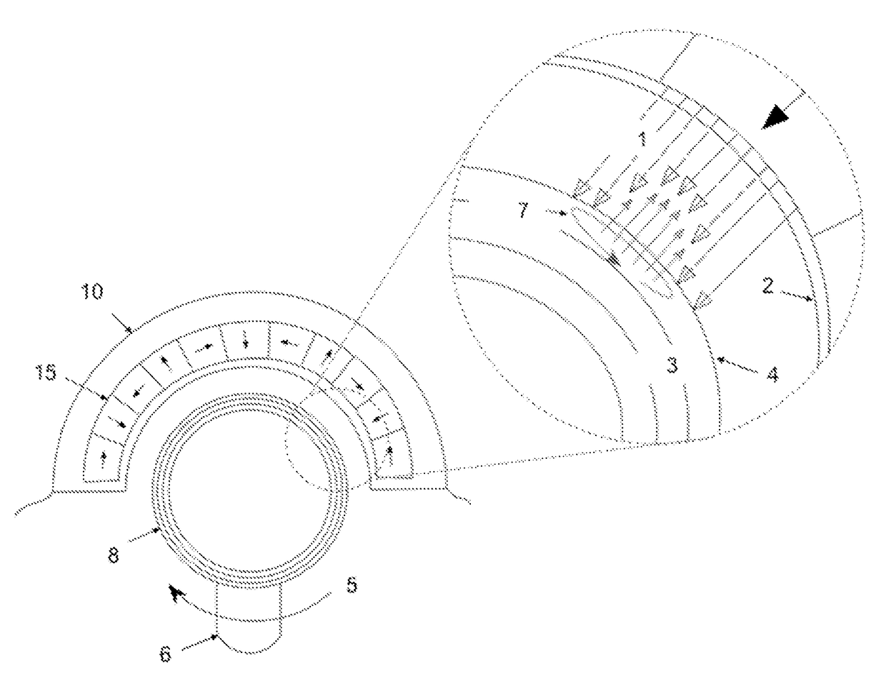
[0031]The application describes a device that incorporates passive electromagnetic induction to reduce friction and, optionally, separate TJR bearing surfaces through the development of a stable, repulsive magnetic force.

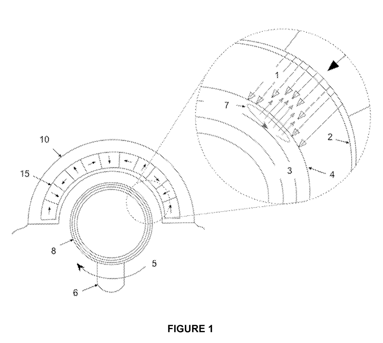
[0032]In one embodiment, the disclosure provides a joint replacement coupling comprising opposing joint surfaces, wherein one of the surfaces has an array of magnets therein, and the other of the surfaces has a conductive surface. The magnets are typically in a magnetic portion located in or below the surface of a member of the coupling. The conductive surface is typically located in or on in a conduction portion of a member of the coupling. The magnets are arranged to produce a magnetic field that contacts the conductive surface, wherein relative motion between the opposing joint surfaces induces current loops in the conductive surface and produces a repulsive force against the magnetic field. This force reduces friction between the joint surfaces, optionally separ...


PUM


Abstract

The disclosure provides a joint replacement coupling comprising joint members with opposing joint surfaces, wherein one of the members has a magnetic portion therein which comprises an array of magnets, and the other of the members has a conduction portion therein that comprises a conductive surface. The magnets are arranged to produce a magnetic field that contacts the conduction portion. The conduction portion is optionally positioned so that at least a portion of the conductive surface contacts the magnetic field so that relative motion between the opposing joint surfaces induces current loops in the conductive surface and produces a repulsive force against the magnetic portion, thereby reducing friction between the joint surfaces, optionally separating the joint surfaces.

Description

CROSS-REFERENCE TO RELATED APPLICATIONS[0001]This application claims priority to US provisional application no. 61 / 762,516, filed Feb. 8, 2013, which is incorporated by reference herein in its entirety.TECHNICAL FIELD[0002]This invention is related to the field of wear reduction, and reducing the production of wear particles, in total joint replacement by the use of magnetic repulsion between opposing bearing surfaces.BACKGROUND[0003]Current total joint replacement (“TJR”) designs—though tremendously successful in patients with limited activity levels and lifespan—are not optimal for the increasing population of more active and younger patients with advanced degenerative joint disease. These patients have a higher likelihood of implant failures secondary to an inflammatory response initiated by wear particle debris. A new approach in TJR design which minimizes the generation of wear particles through the reduction of frictional forces within the joint is required to address the uniq...

Claims


Application Information

Patent Timeline
IPC IPC(8): A61F2/30A61F2/32A61F2/38A61F2/42
CPCA61F2/32A61F2/38A61F2002/30598A61F2002/30649A61F2002/30079A61F2/4202A61F2002/30054A61F2/3094A61F2/3609A61F2002/30052A61F2002/30971A61F2002/3611A61F2/482A61F2002/30594
Inventor HOWARD, JASON
Owner HOWARD JASON
Why Eureka
Try Eureka