
Parallel assembly of chromatography column modules

a chromatography column and module technology, applied in the direction of separation processes, instruments, mechanical equipment, etc., can solve the problems of increasing the overall footprint of the equipment, increasing the overall cost of the chromatography column, so as to achieve flexible and scalable chromatography

Active Publication Date: 2018-04-17
CYTIVA BIOPROCESS R&D AB
View PDF34 Cites 2 Cited by
  • Summary
  • Abstract
  • Description
  • Claims
  • Application Information

AI Technical Summary

Benefits of technology

The invention is a flexible and scalable chromatography system that can be easily assembled and configured. It consists of a parallel assembly of column modules connected inside a rigid housing, which eliminates the need for extra fluid manifolds. The system is designed to provide good performance with minimal fluid resistance and a low footprint. The parallel assembly can be easily joined to create a larger column, with costs and weight reduction. Overall, the invention allows for efficient and effective chromatography separation.

Problems solved by technology

However, there are a number of problems associated with this concept when using chromatography columns of prior art.
One of the problems is that space requirements increase when using an arrangement of multiple columns configured in parallel, hereby increasing the overall footprint of the equipment when compared to the use of a single larger standard column.
Another problem is that overall cost increases significantly when using a number of smaller prior art columns in parallel configuration compared to using a single large column.
This problem is related to the fact that all individual columns of prior art that would be used in a parallel configuration need to provide mechanical rigidity in order to comply with design standards and pressure equipment directives.
Yet another problem is that fluid manifolds are required to connect the multiple columns in parallel, hereby increasing the overall complexity and cost of the installation.

Method used


Image

  • Parallel assembly of chromatography column modules
  • Parallel assembly of chromatography column modules
  • Parallel assembly of chromatography column modules

Examples


Embodiment Construction

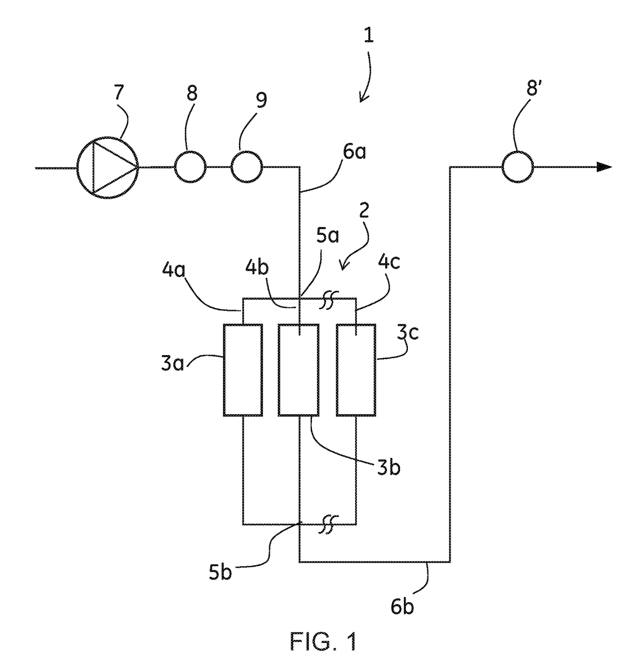
[0034]FIG. 1 shows schematically a flow scheme for a separation system 1 comprising a parallel assembly 2 of three chromatography column modules 3a, 3b, 3c according to one embodiment of the invention. The number of parallel connected column modules can also be two or more than three. The parallel assembly 2 comprises in this example three parallel fluid paths 4a, 4b, 4c. Each fluid path 4a, 4b, 4c comprises one column module 3a, 3b, 3c. One assembly inlet 5a defines a common fluid inlet to the parallel assembly 1 and one assembly outlet 5b defines a common fluid outlet from the parallel assembly 2. The separation system 1 comprises further an inlet fluid path 6a connecting to the assembly inlet 5a and an outlet fluid path 6b connecting to the assembly outlet 5b. The inlet fluid path 6a comprises in this embodiment a pump 7, a flow meter 8 and a pressure sensor 9. Alternatively the flow meter could be positioned downstream the parallel assembly 3, which is shown as flow meter 8′. In...


PUM

PropertyMeasurementUnit
thicknessaaaaaaaaaa
flow rateaaaaaaaaaa
flow rateaaaaaaaaaa

Abstract

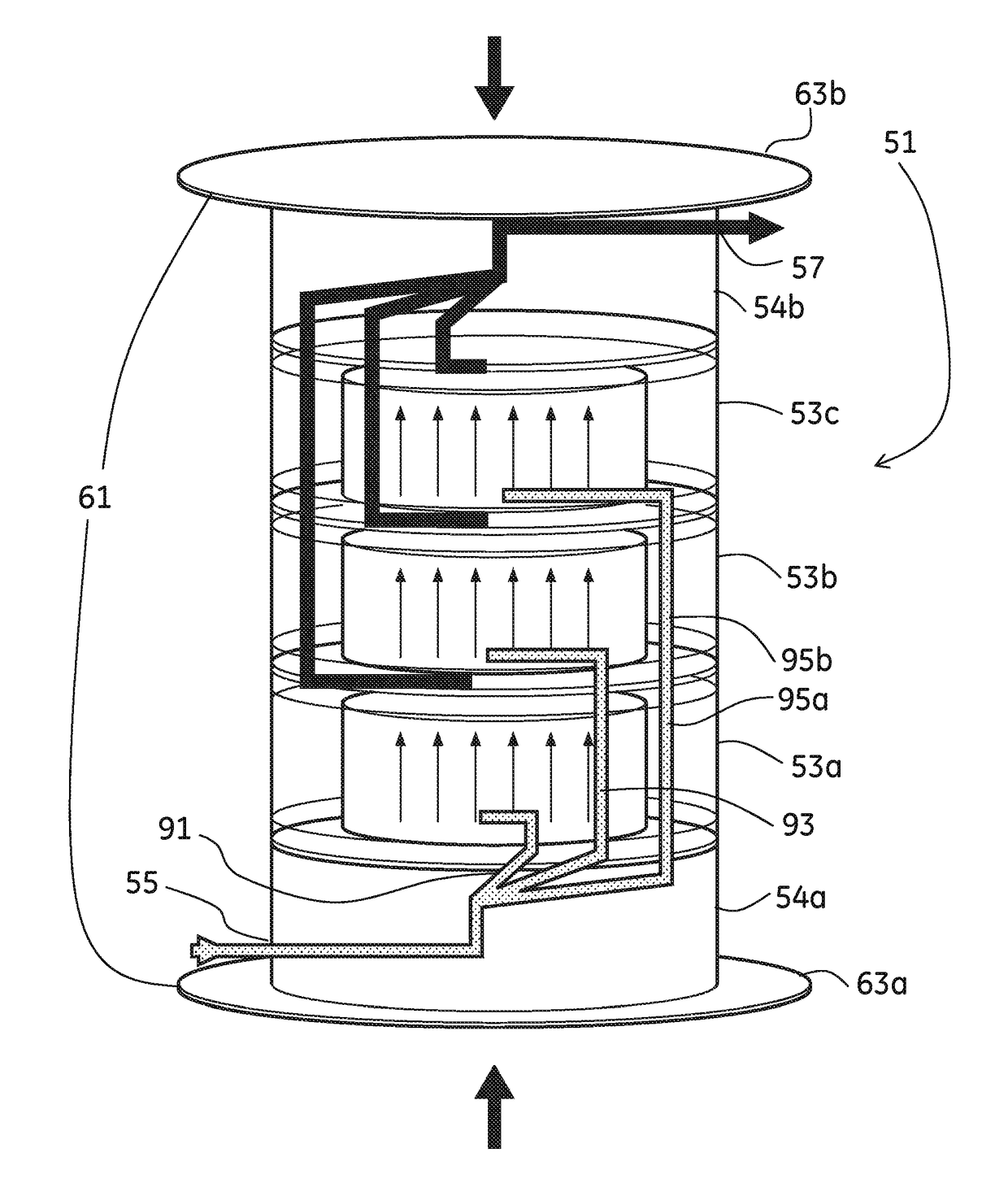
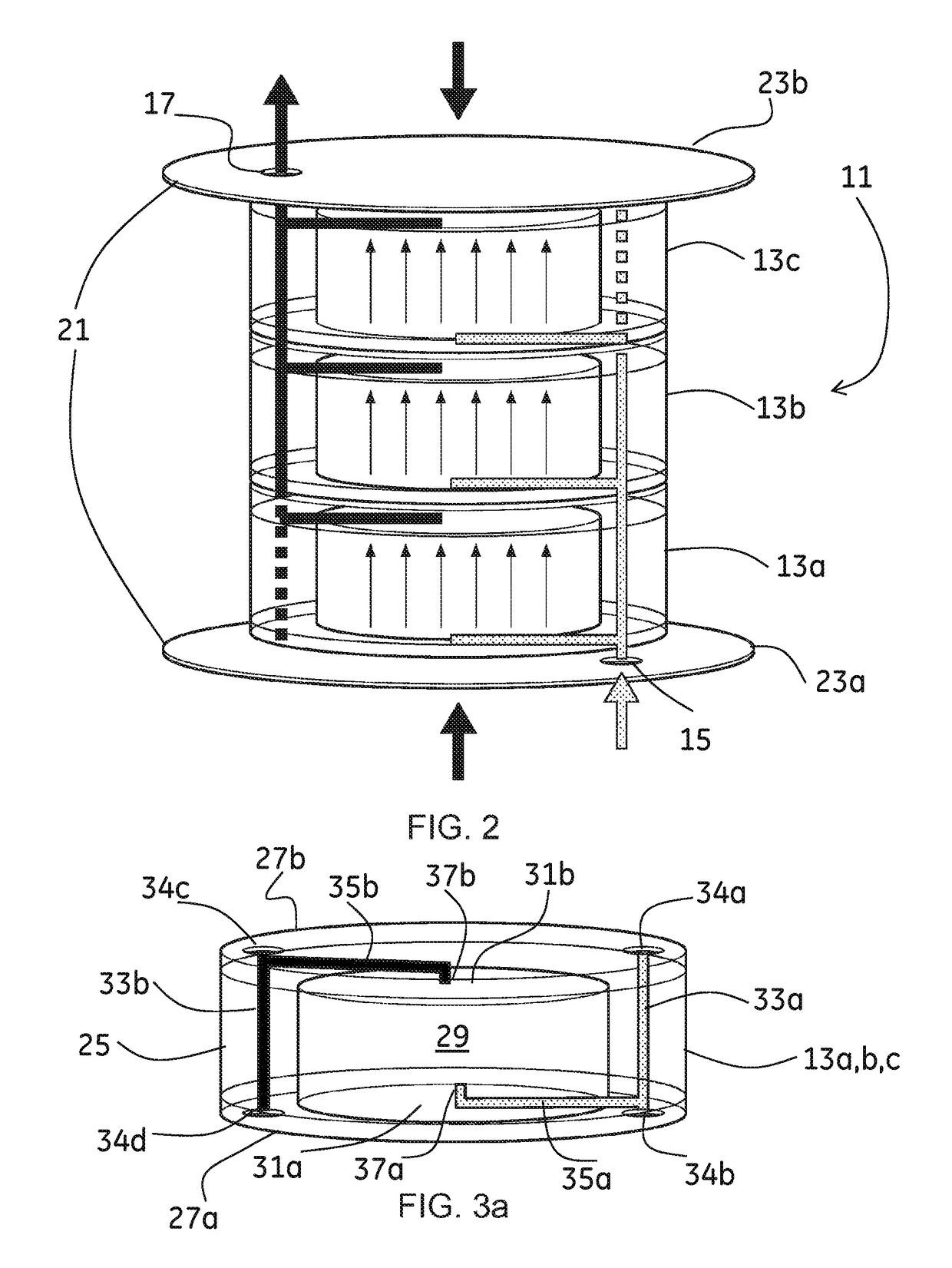
A parallel assembly (2; 11; 51) of chromatography column modules (3a,b,c; 13a,b,c; 53a,b,c, 90a, b) connected in a rigid housing (21; 61), the assembly having one common assembly inlet (15; 55) and one common assembly outlet (17; 57), each column module comprising a bed space (29) filled with chromatography medium and each column module comprises integrated fluid conduits which when the column module is connected with other column modules in the rigid housing are adapted to connect the bed space (29) of the column module with the assembly inlet (15; 55) and the assembly outlet (17; 57), wherein the total length and / or volume of the fluid conduit from the assembly inlet to one bed space together with the length and / or volume of the fluid conduit from the same bed space to the assembly outlet is substantially the same for all bed spaces and modules installed in the parallel assembly.

Description

CROSS-REFERENCE TO RELATED APPLICATIONS[0001]This application is a filing under 35 U.S.C. 371 of international application number PCT / SE2011 / 050681, filed Jun. 1, 2011, published on Dec. 8, 2011 as WO 2011 / 152788, which claims priority to application number 1050565-9 filed in Sweden on Jun. 3, 2010.TECHNICAL FIELD OF THE INVENTION[0002]The present invention relates to a parallel assembly of chromatography column modules, a chromatography column module adapted to be used in a parallel assembly, a rigid housing adapted to hold any number of chromatography column modules and to a method for connecting chromatography column modules in a rigid housing.BACKGROUND OF THE INVENTION[0003]The use of separation modules, such as chromatography columns or cartridges, in a parallel configuration has a potential to increase flexibility in pilot and process scale bio-manufacturing. Flexibility is increased by the ability to build a larger system of required capacity from a number of standardized mo...

Claims


Application Information

Patent Timeline
Patent Type & Authority Patents(United States)
IPC IPC(8): B01D15/22B01D15/18G01N30/60F16L55/00G01N30/46
CPCB01D15/22B01D15/1864F16L55/00G01N30/466G01N30/6004G01N30/461Y10T29/49826B01D15/1885
Inventor GEBAUER, KLAUSRAMAKRISHNA, MANOJ KUMARSALOMONSSON, DANIELUSELIUS, PER
Owner CYTIVA BIOPROCESS R&D AB
Learn More