Minimal reactance vehicular antenna (MRVA)

a vehicular antenna and reactance technology, applied in the field of communication antennas, can solve the problems of a number of limitations and shortcomings of current antennas

Inactive Publication Date: 2018-04-10
THE UNITED STATES OF AMERICA AS REPRESENTED BY THE SECRETARY OF THE NAVY
View PDF10 Cites 4 Cited by
  • Summary
  • Abstract
  • Description
  • Claims
  • Application Information

AI Technical Summary

Problems solved by technology

Current antennas have a number of limitations and shortcomings.

Method used


Image

  • Minimal reactance vehicular antenna (MRVA)
  • Minimal reactance vehicular antenna (MRVA)
  • Minimal reactance vehicular antenna (MRVA)

Examples


Embodiment Construction

[0018]Disclosed herein are various embodiments of an antenna 10 having an improved design. The antenna 10 below may be described generally herein, as well as in terms of specific examples and / or specific embodiments. For instances where references are made to detailed examples and / or embodiments, it should be appreciated that any of the underlying principles described are not to be limited to a single embodiment, but may be expanded for use with any of the other methods and systems described herein as will be understood by one of ordinary skill in the art unless otherwise stated specifically.

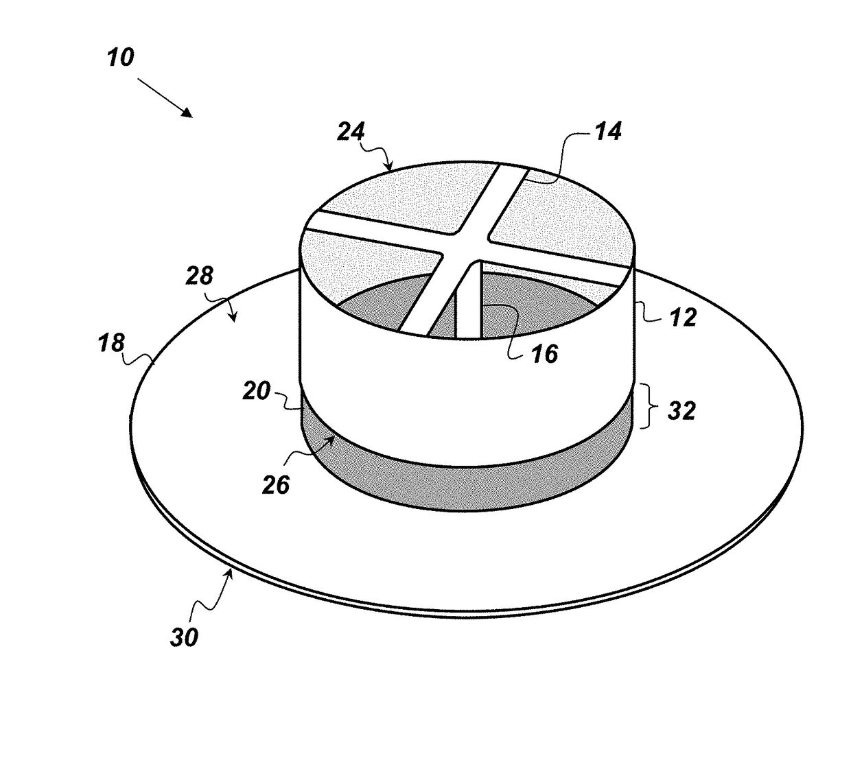
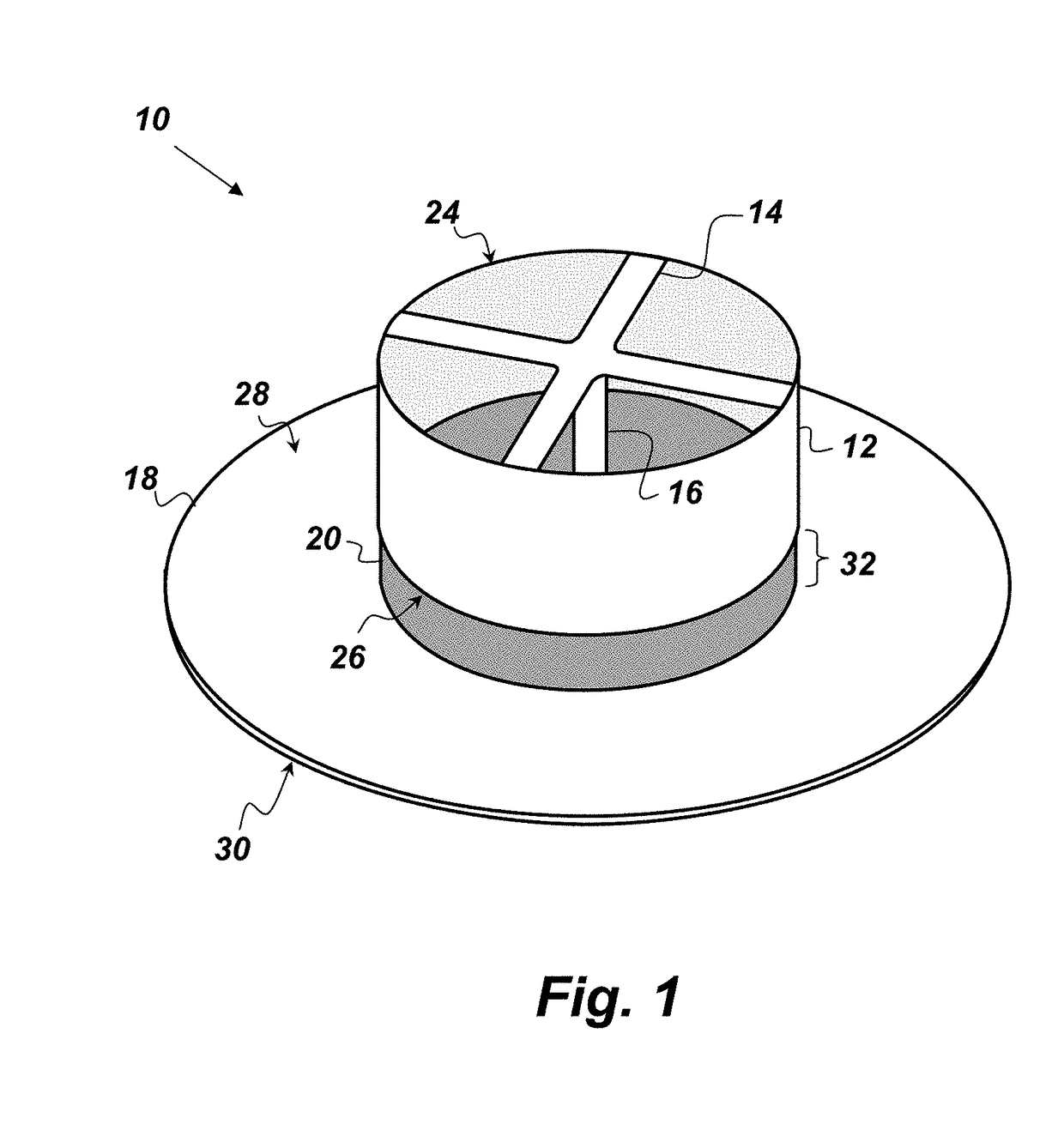
[0019]FIG. 1 is an oblique view illustration of an embodiment of the antenna 10 that comprises, consists of, or consists essentially of a chamber 12, a shorting strap 14, a center member 16, a ground plane 18, and a first insulator 20. The chamber 12 is hollow and conductive and has an upper end 24 and a lower end 26. The lower end 26 of the chamber 12 is open. In other words, the lower end 26 i...


PUM


Abstract

An antenna comprising: a hollow conductive chamber having an upper end and a lower end, wherein the lower end is open; a shorting strap electrically connected to the upper end; a conductive center member running through the chamber and electrically connected to the shorting strap; a conductive ground plane having a top surface and a bottom surface, wherein the top surface is separated from the lower end of the chamber by a gap; and a first solid insulator connected to the chamber and the top surface of the ground plane such that the first insulator fills the gap and fills the lower end and an interior portion of the chamber.

Description

FEDERALLY-SPONSORED RESEARCH AND DEVELOPMENT[0001]The United States Government has ownership rights in this invention. Licensing and technical inquiries may be directed to the Office of Research and Technical Applications, Space and Naval Warfare Systems Center, Atlantic, Code 72000; voice (843) 218-3495; ssc_lant_t2@navy.mil. Reference Navy Case Number 103302.BACKGROUND OF THE INVENTION[0002]The invention described herein relates to the field of communications antennas. Current antennas have a number of limitations and shortcomings. There is a need for an improved antenna.SUMMARY[0003]Disclosed herein is an antenna comprising: a hollow conductive chamber, a shorting strap, a conductive center member, a conductive ground plane, and a first solid insulator. The conductive chamber has an upper end and a lower end, and the lower end is open. The shorting strap is electrically connected to the upper end. The conductive center member runs through the chamber and is electrically connected...

Claims


Application Information

Patent Timeline
Patent Type & Authority Patents(United States)
IPC IPC(8): H01Q1/32H01Q1/48H01Q9/36
CPCH01Q1/3275H01Q9/36H01Q1/48
Inventor GARDNER, CHAD MICHAELCRAWLEY, KEN ALLEN
Owner THE UNITED STATES OF AMERICA AS REPRESENTED BY THE SECRETARY OF THE NAVY
Why Eureka
Try Eureka